WS831DL WIRELESS DATA LOGGING
WEATHER STATION
USER’S MANUAL
INTRODUCTION
Thank you for purchasing General’s Data Logging Wireless
Weather Station. This compact and easy-to-use product
uniquely measures and monitors weather data right at
your immediate location.
It includes a wide range of weather features plus precise
atomic time and perpetual calendar. Weather
measurements include: air temperature, relative humidity,
barometric pressure, wind speed and direction,
rainfall levels and more.
PACKAGE CONTENTS
In this package you will find:
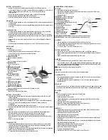
• One Main Unit (receiver)
• One Rain Gauge (remote rain sensor/transmitter)
• One Anemometer (remote wind sensor/transmitter)
• One Three-Channel Temperature & Humidity Sensor (transmitter)
• One 7.5V AC/DC Adapter
• One CD-ROM disk
• One 6 ft (2m) USB cable
• Mounting Hardware with wrench tool
• One User’s Manual
Required for installation (not included)
- Small Phillips screwdriver
- Anemometer mounting pole
- Small paper clip to reset sensors
NOTE:
If any items are missing or damaged, please contact Customer Service before proceeding with
installation.
INSTALLATION
General’s Wireless Data Logging Weather Station operates at 433MHz radio frequency, so no wire
installation is required between the main unit (receiver) and the remote weather sensors (transmitters).
The remote weather sensors include (2) thermo-hygrometer (temperature and humidity) sensors,
anemometer (wind sensor) and a rain gauge (rain sensor). All data measured by these remote sensors
is transmitted to the main unit wirelessly, with the operating range up to 328 feet (100 meters) in the
open area. The Anemometer and a rain gauge must be placed outdoors to measure weather elements.
Remote thermo-hygrometers can be placed indoors or outdoors. If you intend measuring outdoor
temperature and humidity, place the remote sensor outdoors, preferably not in the direct sunlight.
BEFORE YOU BEGIN
The components of this complete Wireless Weather Station operate wirelessly at 433MHz radio
frequency.
No interconnecting wires are required between the main unit (receiver) and the remote sensors
(transmitters). Power up and test communications between all of the sensors and the main unit
BEFORE
mounting them outside.
• For most applications alkaline batteries are acceptable where temperatures remain above 32°F
(0°C).
• Avoid using rechargeable batteries. (Rechargeable batteries do not provide correct power levels).
•
ALWAYS
install batteries in the remote sensors before the main unit.
• Insert batteries matching the polarity in the battery compartment.
• Remove plastic sleeve from LCD display (if any).
• During an initial setup, place the main unit close to the remote sensors.
• After reception is established (all of the remote readings will appear on the main unit’s display),
position the remote sensors and the main unit within the effective transmission range of up to 328
feet (100 meters). Ideally they should be placed within the line of sight of the main unit. See
placement tips in the user manual for each remote sensor.
• Transmission range may be affected by trees, metal structures and electronic appliances.
• The main unit must be placed indoors.
• The effective operating range may be influenced by the surrounding building materials and how
the receiver (main unit) and transmitters (sensors) are positioned.
• Place the remote sensors so that they face the main unit (receiver), minimizing obstructions such as
doors, walls, and furniture.
• Make sure that the remote sensors are easily accessible for cleaning and maintenance.
NOTE:
When the temperature falls below freezing, the outdoor sensor batteries may have reduced
voltage and a reduced effective range. We recommend using lithium batteries at temperatures
below 32°F (0°C).
IMPORTANT:
We recommend cleaning the remote sensors periodically, as dirt and debris affects sensor
accuracy.
THERMO-HYGROMETER SENSOR
FEATURES
• LCD display of measured temperature and humidity.
• Remote data transmission to the main unit via 433 MHz signal.
• 328 feet (100 meters) transmission range without interference.
• Three (3) transmission channels selection.
• Case can be wall mounted using built-in hanger.
A. LED INDICATOR
• Flashes once when the remote sensor transmits a reading to the main unit.
• Flashes twice when battery power is low.
B. BATTERY COMPARTMENT
• Holds 2 “AA” batteries. (not included)
C. RESET
• Resets all readings (requires small
paper clip.)
D. CHANNEL SWITCH
• Selects the desired sensor channel from
1 to 3.
E. WALL-MOUNT RECESSED OPENING
• Keeps the remote sensor on the wall.
NOTE:
Install the batteries and select the
channel before mounting the sensor.
A
C
E
F
D
B


