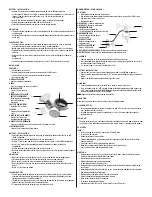
G
D
C
F
H
E
A
B
BATTERY INSTALLATION
• Remove the screws from the battery compartment with a small Phillips screwdriver.
• Set the channel 1 through 3. The switch is located in the battery compartment. Set one sensor to
Channel 1 and the second sensor to Channel 2, etc. The sensors must operate on
separatechannels.
• Install 2 “AA” batteries matching the polarities shown in the battery compartment.
• Replace the battery compartment door and secure the screws.
• Secure the thermo-hygrometer remote sensor in the desired location.
MOUNTING
• The remote thermo-hygrometer sensor can be placed on the flat surface or mounted on the wall in
vertical position.
• Use the wall mount hardware and screws provided when mounting the thermo-hygrometer sensor
on the wall.
PLACEMENT TIPS:
• The remote thermo-hygrometer sensor should be placed in the area with a free air circulation
and sheltered from the direct sunlight and an extreme weather conditions.
• Ideally, place the thermo-hygrometer sensor above the natural surfaces (such as a grassy lawn).
• Avoid placing the thermo-hygrometer sensor near sources of heat such as chimneys and heating
elements.
• Avoid areas that collect or radiate heat from the sun, such as metal, brick/concrete structures,
paving,
or patio decks.
• The best location for temperature measurements is 4 feet (1.25meters) above the ground.
RAIN GAUGE
FEATURES
• Precipitation measurement.
• Remote rainfall data transmission to the main unit via 433 MHz signal.
• 100 feet (30 meters) transmission range without interference.
• Built-in installation level.
A. RAIN GAUGE BUCKET
Contains electronic components.
B. KNOB
Secures the top on the rain gauge bucket.
C. RAIN GAUGE FEET
Secures the rain gauge in
place.
D. FUNNEL-SHAPED TOP WITH
BATTERY COMPARTMENT
Contains battery compartment
and rainfall counting
electronics.
E. BATTERY COMPARTMENT
Holds two “AA” batteries.
F. SCREWS
Secures battery compartment
cover.
G. BUILT-IN LEVEL WITH BUBBLE
Ensures level rain gauge
mounting for proper operation.
H. BUCKET SEE-SAW MECHANISM
Collects the rainfall in one of its containers and self-empties once full.
I. PROTECTIVE SCREEN
Protects the rain gauge funnel from debris.
BATTERY INSTALLATION
• Unlock the funnel-shaped top on the rain gauge by turning both knobs on the sides in an anti-
clockwise direction.
• Remove the funnel-shaped top lifting it off the rain gauge bucket.
• Remove 7 small screws from the battery compartment cover using a small Phillips screwdriver.
• Insert 2 “AA” batteries (not included), matching the polarities as shown in the battery
compartment.
• Replace the battery compartment door and secure the screws.
• Insert the funnel-shaped top into the rain gauge bucket and secure it in place by turning the knobs
clockwise.
MOUNTING
• Make sure that the rain gauge bucket is level – check inside built-in level for bubble center.
• Place the protective screen over the top to protect the rain gauge from the debris.
• Where practical, mount the rain gauge in place with wood screws (not included).
• Make sure that the rain gauge is in open area where precipitation falls directly into the gauge’s
bucket,
ideally 2-3 feet above the ground.
PLACEMENT TIPS
• The rain gauge should be placed in an open area away from the walls, fences, trees and other
coverings which may reduce the amount of rain falling into the bucket. Additionally, trees and
rooftops may be sources of pollen and debris.
• To avoid the rain shadow effects, place the rain gauge horizontally, on the distance corresponding
to two to four times the height of any nearby obstruction.
• It is important to locate the unit where rain can flow away freely.
ANEMOMETER (WIND SENSOR)
FEATURES
• Wind speed and wind direction measurement.
• Remote wind speed and wind direction data transmission to the main unit via 433 MHz signal.
• Operating range 100 feet (30 meters).
• Wall or pole mount.
A. WIND VANE -
Indicates wind direction.
B. WIND CUPS -
Measures wind speed.
C. ANEMOMETER BASE
• Holds battery compartment.
• Allows mounting the anemometer vertically.
D. ANEMOMETER ARM
Connects battery to anemometer
head assembly.
E. WIND CUPS SHAFT
Holds wind cups on the a
nemometer arm.
F. BATTERY COMPARTMENT
Holds 2 “AA” batteries.
G. WALL MOUNT SCREW OPENINGS -
Allows securing the anemometer in place.
H. BATTERY COVER -
Secures battery compartment on the anemometer base.
ASSEMBLY
• Slide the wind cups on to the anemometer rotating shaft. Do not use force.
• Insert the Allen Wrench (provided) into the wind cup set screw opening. Tighten the set screw to
secure wind cups to the rotating shaft.
• Test to ensure cups are securely fastened to the shaft.
BATTERY INSTALLATION
• Remove four (4) screws from the battery compartment with a small Phillips screwdriver.
• Open the battery compartment and install 2 “AA” batteries (not included) matching the polarities
shown.
• Replace the battery compartment door and secure the screws.
ALIGNING
• Point the wind direction vane to the north (use a compass or map if necessary).
• Press the button inside the “
SET
” opening located inside battery compartment with a paper clip.
“
SET
” selects a new direction for
NORTH
and, when pressed repeatedly, alternates between the
factory default
NORTH
and user selected
NORTH
.
NOTE:
Repeat this procedure after changing the batteries.
MOUNTING
Mount the anemometer onto a vertical surface, using the fittings provided.
PLACEMENT TIPS:
• The anemometer should be mounted in an open area with a free air flow; away from the nearby
trees, buildings or other structures.
• For optimal performance, mount the anemometer at 33 feet (10meters) above the ground in
unobstructed area.
MAIN UNIT
The main unit measures pressure, indoor temperature, humidity, and receives atomic time data from
the US Atomic Clock and outdoor measurements from remote sensors. It should be placed indoors.
FEATURES
TIME
• Precise time and date set via RF signals from US Atomic clock.
• 12 or 24 hour time format.
• Manual adjustment of time and date.
• Calendar displaying date with month and day in 6 languages English, German, French, Italian,
Spanish and Dutch.
• Time Zones for over 100 pre-programmed world cities.
• Moon Phase calendar and historical data for the past and future 39 days.
• Dual crescendo alarms with programmable snooze.
WEATHER
• Weather forecast for the next 12 to 24 hour in seven large icons: Sunny, Partly Cloudy, Cloudy,
Light Rain, Heavy Rain, Unstable Weather and Snowy.
• Barometric pressure in imperial or metric units.
• Altitude adjustment for pressure compensation.
• 24 hour barometric pressure history chart.
• Multiple weather alerts including: Hi/Low temperature, Daily Rainfall, Hi wind gust and Hi wind
speed alerts.
• Indoor/Outdoor Temperature & Humidity in up to 3 remote locations (additional sensors required).
• Dew point and comfort level indicators.
• Wind direction, speed and wind gust averages and memory.
• Rainfall amount with minimum and maximum memory.
• 200 weather records without PC connection.
• PC software (included) and USB port.
• Operating range from 100 feet (30 meters) up to 328 feet (100 meters).
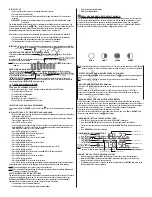
D
G
H
I
E
F


