background image


GENEREX SYSTEMS Computervertriebsgesellschaft mbH - www.generex.de -   21  

GENEREX Systems Inc. -  www.generex.us      


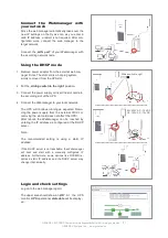
Connect  the  Webmanager  with 
your network  

Since the web manager automatically takes over the 
new  IP  settings  on  the  fly  as  soon  as  you  enter  a 
valid IP address, a restart is not required. After con-
figuration  work,  connect  the  web  manager  to  the 
target network. 
 
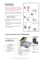
Connect  the  „

LAN  port

“  of  your 

Webmanager

  with 

the  accord ing network node. 


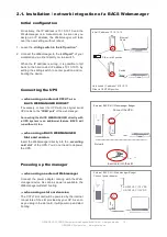
Using the DHCP mode 

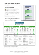
1.  Remove power adapter from the external web ma-

nager. Since The slot card is a hot plug system, 
simply remove it from the UPS slot. 
 

2.  Put the „

sliding switch to the right

“ position. 


3.  Connect the power supply or insert the slot card into 

the according slot of the UPS 
 

4.  Connect the 

Webmanager

 to your local network. 


The UPS will continue running as expected. Remo-
ving  the  power  supply  from  the  external 

CS141

  or 

removing the slot card does not affect the UPS! 
After  reboot,  the 

Webmanager

  can  be  reached  by 

entering the IP address as configured at the DHCP 
server. 
 
Note: 
 
The  recommended  setting  is  using  a  static  IP 
address: 
 

 If the DHCP server is not reachable, the 

Webmanager


will  boot  and  start  with  a  manually  configured  IP 
address.  Furthermore,  some  options  like  RCCMD  re-
quires  a  static  IP  address  and  the  DHCP  server  may 
change it dynamically. 


Login and check settings 

Log on to the web manager again: 
 
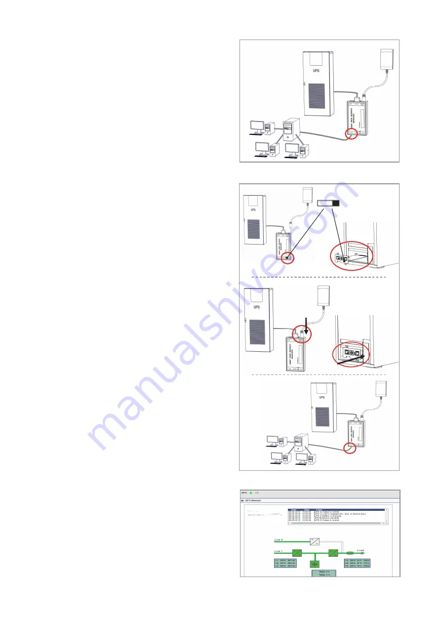
The upper area should show an „

OK

“.  At  the  UPS 

monitor, 

UPS 

operational 

state data 

will be display-

ed.   


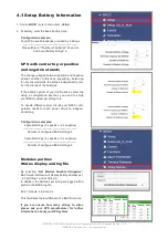
Sliding switch to right  

EU: 230V AC / 12 V DC 
US: 120V AC / 12V DC 

Summary of Contents for BACS System

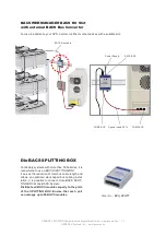
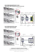
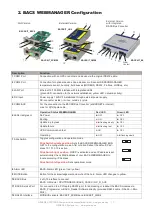
Page 1: ...Components BACS Measuring Cable BACS Bus Cable BACS Module BACS WEBMANAGER CS141 SNMP Adapter Professional BACS Bus Converter BACSKIT_BSC4 Slot Version BACSKIT_LB4 External Box CS141 SNMP Adapter MODB...

Page 2: ...with EN 50272 2 2001 Safety Re quirements for Secondary Batteries and Battery Installations Part 2 Stationary Batteries IEEE Standard 450 2002 Recommended Practice for Maintenance Testing and Replace...

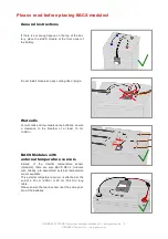
Page 3: ...s after a discharge period BACS modules must NOT be mounted on a damaged battery If a battery is damaged and its internal resistance is high charging current or current being discharged may follow the...

Page 4: ...time frame for reaction to alarms BACS is a tool designed to increase the durability of accumulators but its most important function is to monitor the battery in order to avoid breakdowns For this rea...

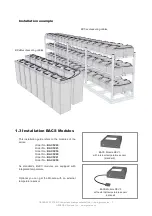
Page 5: ...ry the surface of the ac cumulator with an antistatic fabric 1 2 Installation BACS Measuring Cables Please follow the installation diagrams on the next pages to mount the cables correctly to the batte...

Page 6: ...BACS test lead to all poles Note If the battery has more than 4 poles it is sufficient to connect the BACS cable to four battery poles Use the same poles at each battery Note Please refer to the batte...

Page 7: ...Order No BACSC23 Order No BACSC30 Order No BACSC40 Order No BACSC41 Order No BACSC50 As standards BACS modules are equipped with integrated temperature Optional you can get the Module with an externa...

Page 8: ...cooling ribs or plugs Wet cells For wet cells and low maintenance batteries ensure a clearance to the breather of at least 10 cm 3 94in BACS Modules with external temperature sensors Instead of the i...

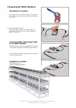
Page 9: ...e Velcro strips 2 Mounting the BACS module Position the BACS module press it firmly with your thumb under high pressure and hold the pressure for about 5 10 seconds Connecting BCx Measuring Cable to t...

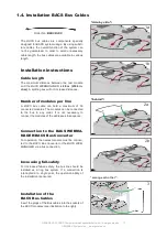
Page 10: ...maximum of 50 connected modules The modules can be connected to the bus in any order It is not necessary to connect the modules of the addresses in sequence Connection to the BACS WEBMA NAGER BACS Bus...

Page 11: ...4 Max cable length from BACS WEBMANAGER to BACS SPLITTING BOX should not exceed 10m 395in Otherwise it will reduce the max length of 6 5 The cable length of the connection between the BACS SPLITTING...

Page 12: ...en the distance of 50m 1970in 8 Max number of BACS Modules is 512 9 Max distance from BACS WEBMANAGER to BACS CURRENT SENSORs should not exceed 10m 395in 10 Max distance between the BACS_GX_R_AUX and...

Page 13: ...ER MODBUS RS485 CS141SCM Slot external BACS Bus Converter Order No BACSKIT_SCMB4 SNMP WEB MANAGER MODBUS RS485 CS141LM external external BACS Bus Converter Order No BACSKIT_LMB4 The BACS Bus Converter...

Page 14: ...generex us Wiring instruction BACS WEBMANAGER BACS WEBMANAGER BACS Kit Box with external BACS Bus Converter BACS Bus cables Power Supply BACS BUS Special cable RJ12 BACS BUS Power Supply Power Supply...

Page 15: ...allows an optimized star shaped bus cabling instal lation It is possible to connect more BACS SPLIT TING BOX at one BACS System Distribute all BACS modules equally to the ports of the SPLITTING BOX E...

Page 16: ...Converter BACS Buskabel BACS Bus cable BACS WEBMANAGER Budget with BACS SPLITTING BOX Installation of the BACS hardware complete For operational mode the BACS modules need to be configured BACS Bus ca...

Page 17: ...12 6pole cable 6 LEDs red green Operation Status WEBMANAGER Red LED Green LED No Power OFF OFF Booting ON OFF Update in progress flashing slowly OFF Update failure flashing fast OFF UPS Communication...

Page 18: ...PS cable to the COM1 port of the web manager Connecting the BACS WEBMANAGER directly with a UPS system is an additional feature BACS will run without it too when using a BACS WEBMANAGER Slot card vers...

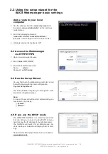
Page 19: ...141 snmp 2 4 Run the Setup Wizard On very first login the Webmanager will start a tool that will help you with the basic configuration System Setup Wizard The Setup Wizard will guide you through the m...

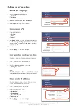
Page 20: ...f you want to use BACS only select No UPS model defined 3 4 Press Apply to save your settings Configure the local system time The time is important for accurate event logging 1 Under System go to Date...

Page 21: ...pply or insert the slot card into the according slot of the UPS 4 Connect the Webmanager to your local network The UPS will continue running as expected Remo ving the power supply from the external CS...

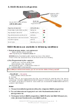
Page 22: ...they are connected to the measuring cable They wake up automatically if the BACS WEBMANAGER BACS Programmer or BACS Reader sends request To wake up the modules it s necessary to activate bus communic...

Page 23: ...er tap using a configuration like that you need to setup your BACS system according to it To handle different power circuits your BACS confi guration needs for each power circuit an indepen dent strin...

Page 24: ...earch Tool Find BACS modules by address 4 2 1 Addressing BACS Modules via Automatic Mode Automatic mode allows automatic addressing of modules After each successful addressing an address is automatica...

Page 25: ...can also press and hold the button on the relevant BACS module for about 10 se conds to reset the module to the delivery state With C20 HW 3 x FW 3 4 1 and C30 C40 HW 3 x from FW 3 4 2 this BACS modu...

Page 26: ...to provide the replacement of broken mo dules as well as adding one single module to the existing configuration Please Ensure only one module is connected to your Manager Entering address Under Old en...

Page 27: ...dialog as expected 1 Remove the power supply from the WEBMANAGER For the slot versions pull the card out of the slot of your UPS 2 To switch the WEBMANAGER to operating mode left position manual IP ri...

Page 28: ...ccessful initialization the BACS status page will be displayed with the voltage and temperature of the batteries the equalization power and the status of the LEDs After approximately 15 minutes the fi...

Reviews: