24
CYLINDER HEAD / VALVES
SERVICE INFORMATION CYLINDER HEAD REMOVAL
TROUBLESHOOTING
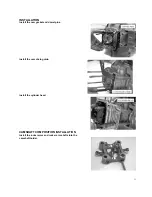
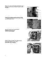
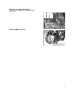
CYLINDER HEAD INSTALLATION
CAMSHAFT COMPOSITION REMOVAL
SERVICE INFORMATION
GENERAL
This section describes cylinder head, valves, camshaft and the other parts maintenance. The engine must be
removed from the frame to service cylinder head. Camshaft lubrication oil is fed to the cylinder head through
an oil orifice in the engine case. Before installing the cylinder head be sure the orifice is not clogged and the
gasket, O-ring and dowel pins are in place.
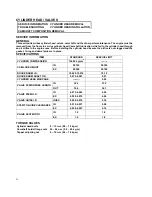
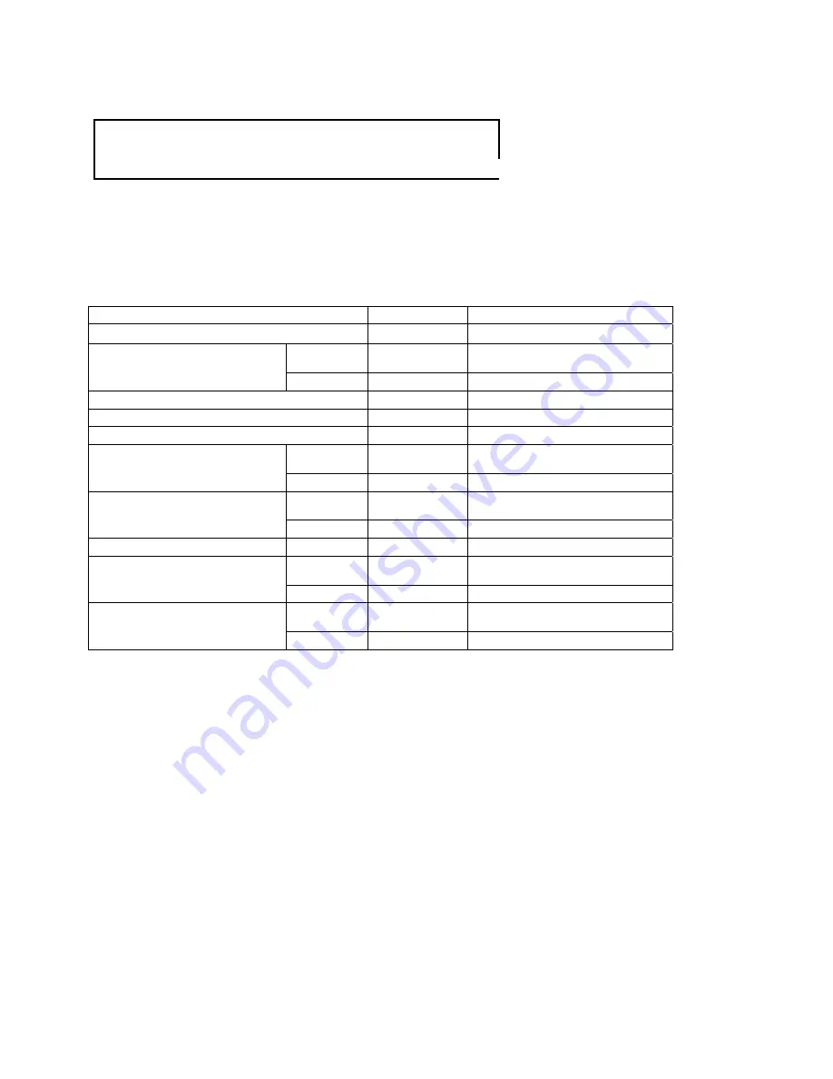
SPECIFICATIONS
ITEM
STANDARD
SERVICE LIMIT
CYLINDER COMPRESSION
12±0.5 kg/cm
2
--------
IN
29.795
29.395
CAM LOBE HEIGHT
EX
29.560
29.160
ROCKER ARM I.D.
10.000-10.018
10.10
ROCKER ARM SHAFT O.D.
9.972-9.987
9.91
CYLINDER HEAD WARPAGE
--------
0.05
IN
32.3
31.2
VALVE SPRING FREE LENGTH
OUT
35.0
34.1
IN
4.975-4.990
4.90
VALVE STEM O.D.
EX
4.955-4.970
4.90
VALVE GUIDE I.D.
IN/EX
5.000-5.012
5.30
IN
0.010-0.037
0.08
STEM-TO-GUIDE CLEARANCE
EX
0.030-0.057
0.10
IN
1.0
1.8
VALVE SEAT WIDTH
EX
1.0
1.8
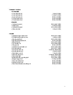
TORQUE VALUES
Cylinder head bolts
8 ~ 12 n-m (0.8 ~ 1.2 kg-m)
Camshaft holder flange nuts 20 ~ 24 n-m (2.0 ~ 2.4 kg-m)
Tappet adjusting nut
9 ~ 12 n-m (0.9 ~ 1.2 kg-m)
Summary of Contents for XOR 125
Page 6: ...5...
Page 20: ...19 14...
Page 43: ...42 CHAPTER 4 FUEL AND LUBRICATION SYSTEM CONTENTS FUEL SWITCH CARBURETOR...
Page 64: ...63 3 Disconnect throttle cable and oil pump cable 4 Remove rear brake cable adjusting nut...
Page 91: ...90 WIRE CABLE AND BRAKE HOSE ROUTING...
Page 92: ...91 carburetor...
Page 93: ...92...
Page 94: ...93 Ignition coil Starting relay CDI HORN POWER SWITCHH...
Page 96: ...95...

