59
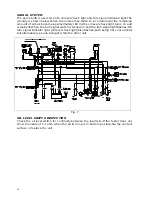
CHARGING AND LIGHTING SYSTEM
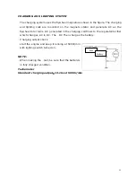
The charging system uses the flywheel magnetoas shown in the figure. The charging
and lighting coils are mounted on the magneto stator and generate AC as the
flywheel rotor turns. AC generated in the charging coil flows to the regulator/recifier
which changes AC to DC. The DC Then charges the battery.
Charging output check
start the engine and keep it running at 5000r/min
with lighting switch turned on.
NOTE:
When making the test, be sure that the batteryis
in fully charged condition.
Tachometer
Standard charging output
:
13-16v at 5000r/min
Fuse
Battery
Summary of Contents for XOR 50 ccm
Page 1: ......
Page 19: ...19 14...
Page 52: ...52 CHAPTER 4 FUEL AND LUBRICATION SYSTEM CONTENTS FUEL SWITCH CARBURETOR OIL PUMP...
Page 73: ...73 3 Disconnect throttle cable and oil pump cable 4 Remove rear brake cable adjusting nut...
Page 86: ...86...
Page 101: ...101 WIRE CABLE AND BRAKE HOSE ROUTING...
Page 102: ...102 carburetor...
Page 103: ...103...
Page 104: ...104 Ignition coil Starting relay CDI HORN POWER SWITCHH...
Page 106: ...106...

