1N00-510 Genesis 80cm Boat v1.1 02/04
©Tornado International Ltd. 2003
-14-
Confidential
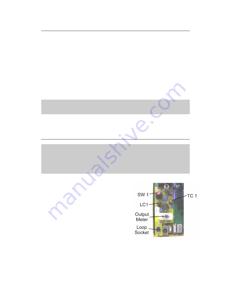
2.11 Loop Output Board
The loop output board (Diagram 2.09) is located next to the transmitter, on the
transmitter motherboard. To operate efficiently all transmitters have to have
an aerial which is of a specific length. (Or equal divisions of that length).
Normally the manufacturer determines the length during development and
makes the aerial accordingly. In the case of our equipment however, the
length of the aerial is determined by the perimeter of the model area. Clearly
there is a conflict of requirements and this is overcome by the use of the loop
output board. This assembly matches the length of loop wire (the aerial) to the
transmitter. This is achieved by changing the capacitance of the circuit. The
procedure of matching the length of the loop wire to the transmitter is called
“Tuning the Loop” and should only be required during installation, if the size of
the operating area is changed or exceptionally if the loop wire is changed.
Tuning the loop is not required if the transmitter is changed for the supplied
spare.
Caution!
Operating the system with the loop partially or incorrectly tuned will lead to
poor model performance and damage to the transmitter and receivers.
The loop output board has a secondary function, that of providing a loop
output meter which is used to tune the loop and check on the performance of
the transmitter during service.
2.12 Tuning the Loop
Caution!
This procedure is vital to the operation of the equipment. It should only be
carried out by a technician who is fully conversant with the principal behind
the procedure and has read and understood the following instructions.
Operating the system with the loop partially or incorrectly tuned will lead to
poor model performance and damage to the transmitter and receivers.
1. Remove the cover from the transmitter
motherboard.
2. Locate the adjusters SW1 & TC1.
3. Check that the loop plug is securely
connected to the loop socket.
4. Check that every playing position has a
red light showing and that each credit
display is showing “0”.
5. Check that the fault LED in the master
console is not on. If it is check to ensure
that every console socket has a plug
connected.
6. Rotate SW1 fully anti-clockwise and
observing the loop output meter select each clockwise position in turn,
noting the loop output meter reading at each position.
Note: If the loop output meter should read over 10 during this procedure
adjust LC1 to return the needle to 5. Please read the note and instructions
below before doing this.


