background image

© 2020 Genesis Attachments, LLC

Genesis Rail Breaker GRB 30

10

Know the Work Area

Check clearances in the work area. Keep all bystanders at a safe distance. Do not work under 

obstacles. Always check your location for overhead and buried power lines or other utilities before 

operation.

Check ground conditions. Avoid unstable or slippery areas. Position the carrier on firm level 

ground. If level ground is not possible, position the carrier to use the attachment to the front or 

back of the carrier. Avoid working over the side of the carrier.

To reduce the risk of tipping and slipping, never park on a grade exceeding 10% (one-foot rise 

over the span of a ten-foot run).

Starting Procedure

Before operating, walk completely around the equipment to make certain no one is under it, on it 

or close to it. Keep all bystanders at least 75 feet away from the area of operation and equipment 

movement. Let all other workers and bystanders know you are preparing to start. DO NOT operate 

until everyone is clear.

Always be properly seated in the operator’s seat before operating any carrier controls.

To start:


3

Make sure all controls are in the center (neutral) position.


3

Be properly seated.


3

Slowly operate all functions to check for proper operation and to bleed air from the hydrau-

lic system.

To shut down:


3

Return your Genesis attachment to a rest position on the ground.


3

Shut off the carrier engine.


3

Work controls in all directions to relieve hydraulic pressure, per excavator manufacturer’s 

instructions.

!

WARNING

Serious injury or death could result if warnings or 

instructions regarding safe operation are not followed 

properly.

Place the Load Safely

Do not move the attachment, or anything held in the jaws, over people, equipment or buildings. Do 

not throw or drop the contents. Operate the controls smoothly and gradually.

OPERATIONAL SAFETY

Summary of Contents for GRB 30

Page 1: ...Rail Breaker GRB 30 SAFETY OPERATOR S MANUAL The GRB 30 processes 136 lb and smaller low chrome rail ...

Page 2: ... mail tchoo genesisattachments com Europe Africa Middle East Genesis GmbH Teramostrasse 23 87700 Memmingen Germany Phone 49 83 31 9 25 98 0 Fax 49 83 31 9 25 98 80 genesis europe com E mail info genesis europe com Central America Colombia Cra 13A 89 38 Ofi 613 Bogota Colombia Phone 57 1 610 8160 795 8747 E mail contact themsagroup com Genesis Attachments 1000 Genesis Drive Superior WI 54880 USA To...

Page 3: ...he Warranty Registration Form must be filled out by the dealer or customer and returned to Gen esis indicating the date the attachment went into service Possible Variations Genesis cannot anticipate every possible circumstance that might involve a potential hazard as the owner s requirements and equipment may vary Therefore the warnings in this publication and on the product may not be all inclusi...

Page 4: ...nt 12 Equipment Condition 12 Working Overhead 12 Power Lines 12 Use Care with Hydraulic Fluid Pressure 13 Prioritized Oil Flow 14 Emergency Situations 14 Unsafe Conditions 14 Crystalline Silica Dust 14 Process Material Safely 15 Lift the Load Safely 15 Place the Load Safely 15 ATTACHMENT NOMENCLATURE 16 ATTACHMENT INSTALLATION 18 Dual Pump Flow 18 Installation Procedure 18 CASE DRAIN 20 Rotation C...

Page 5: ...GUIDELINES 38 Welding Ground Clamp 38 Welding Rules 38 BUILD UP 39 Areas to be built up 39 Grind material flush 39 Straight edge 39 HARD SURFACING 40 HARD SURFACING PATTERNS 41 Grain 41 HYDRAULIC ROTATION MAINTENANCE 42 Hydraulic Requirements 42 Rotation Valve Input 42 SLEWING RING MAINTENANCE 43 ROTATION MOTION CONTROL VALVE ADJUSTMENT 44 Adjusting the Rotation Motion Control Valve 44 TROUBLE SHO...

Page 6: ... Genesis Attachments LLC Genesis Rail Breaker GRB 30 6 PARTS ORDER FORM 49 CONTACT INFORMATION 50 TABLE OF CONTENTS For bolt torque specs see the Genesis Fastener Manual genesisattachments com manuals NOTICE ...

Page 7: ...n result in injury or death This statement is used where serious injury or death could result if the instructions are not followed properly WARNING This statement is used where minor or moderate injury could result if the instructions are not followed properly CAUTION This statement is used where property damage could result if the instructions are not followed properly NOTICE DANGER This statemen...

Page 8: ...ove and replace any damaged or worn parts Before Operating 3 Warn all others in the area that you are about to start operation 3 Perform the Check the Equipment steps outlined in this manual 3 Check underneath and around the machine Make sure all personnel and equipment are clear from the area of operation and equipment movement Check clearances in all direc tions including overhead 3 Be properly ...

Page 9: ... retaining bolts 3 Check cylinders for dents barrel or dings rod GOOD CONDITION P WARNING Serious injury or death could result if warnings or instruc tions regarding carrier stability and the work area are not followed properly Stability Your Genesis attachment is sized for carrier stability However improper operation faulty mainte nance or unauthorized modifications may cause instability 3 Know t...

Page 10: ...t least 75 feet away from the area of operation and equipment movement Let all other workers and bystanders know you are preparing to start DO NOT operate until everyone is clear Always be properly seated in the operator s seat before operating any carrier controls To start 3 Make sure all controls are in the center neutral position 3 Be properly seated 3 Slowly operate all functions to check for ...

Page 11: ...hills ridges banks and slopes Avoid operating across a slope which could cause the carrier to overturn 3 Reduce speed when driving over rough terrain on a slope or when turning to avoid overturning the carrier 3 Never use the attachment as a work platform or personnel carrier 3 Keep all step plates grab bars pedals and controls free of dirt grease debris and oil 3 Never allow anyone to be around t...

Page 12: ...g Falling Object Protection Structures or FOPS are neces sary for any application where material is to be handled overhead Transporting the Attachment 3 Travel only with the attachment in a safe transport position to prevent uncontrolled move ment Drive slowly over rough ground and on slopes 3 When driving on public roads use safety lights reflectors Slow Moving Vehicle signs etc to prevent accide...

Page 13: ...injected fluid see a doctor immediately 3 Wear safety glasses and protective clothing and use a piece of cardboard or wood when searching for hydraulic leaks Do Not Use Your Hands See illustration below 3 Hydraulic oil becomes hot during operation Do not let hydraulic oil or com ponents contact skin as it could cause severe burns Allow hydraulic com ponents to cool before working on them Use appro...

Page 14: ...p erations or high reach conditions Emergency Situations Always be prepared for emergencies Make sure a fire extinguisher is available Be familiar with its operation Make sure to inspect and service the fire extinguisher regularly Make sure a first aid kit is readily available Unsafe Conditions Do not operate if an unsafe condition exists Stop operation immediately shut down the machine and report...

Page 15: ... dealer Do not alter hydraulic set tings without consulting an authorized Genesis dealer or the Genesis Service Department Doing so will void the warranty and may cause structural damage accidents or tipping Make sure the load is held securely in the jaws Do not move a loaded attachment if the load is loose or dangling Make sure the load is pinched between the jaws never cradle a load For greater ...

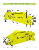
Page 16: ... 2020 Genesis Attachments LLC Genesis Rail Breaker GRB 30 16 ATTACHMENT NOMENCLATURE 6 17 2 7 12 16 18 11 3 4 1 14 9 11 13 8 5 13 15 10 ...

Page 17: ...vot Group Includes the pivot shaft bearings and end caps 9 Lower Jaw Lower part of jaw housing blades 10 Guide Blades Blades mounted on the left side of the attachment designed to eliminate wear on the guide side of the jaw These are not the main cutting blades 11 Blades Upper and lower cutting blades 12 Upper Jaw Moving jaw connected to the cylinder 13 Protection Strips Raised areas of parent mat...

Page 18: ...e on separate sides of the main valve and whether the auxiliary circuit can be proportionally controlled by teeing into the bucket pilot control circuit The auxiliary circuit must also be capable of proportionally controlling pump initiation on the auxiliary side of the circuit On many excavators the auxiliary circuit is controlled by percentage of flow set in the computer This may not control the...

Page 19: ... the excavator cylinder stroke 4 Extend the excavator cylinder until the power link bore lines up with the attachment cylinder pivot connection Pin excavator cylinder to the attachment 5 Crowd and extend the attachment checking closely to make sure there is no interference between the attach ment bracket and hard lines Also check for interfer ence between the cylinder and boom stick 6 Install exca...

Page 20: ...C Genesis Rail Breaker GRB 30 20 CASE DRAIN The GRB 30 rotation system requires an additional case drain line to the tank The case drain line in red can be relocated to either side of the head as required by the excavator pumbing ...

Page 21: ...iary Valve on Machine Rotate Valve Closed center three position spring centered with anti cavitation checks Relief valve setting 1 950 PSI mounted on excavator Hydraulic Motor Motion Control Valve Flow Controls Rotate Work Lines Use 1 2 3000 PSI rated hose Inside Upper Head Case Drain ...

Page 22: ...grams show the installation of the additional circuit Refer to the Hydraulic Rotation Maintenance section of this manual for valve descriptions functions and settings Foot Switch Installation Install the foot switch in the excavator and connect with electrical harness White Normal Open Black Normal Open Red 2 Amp Fuse 24 Volt To Rotator A Black B Green C White Green To Ground ROTATOR INSTALLATION ...

Page 23: ...mp Type Gear Pump Required Rotation Valve Three position tandem center spring centered with anti cavi tation checks Relief Setting 1950 mounted on excavator Hydraulic Motor Motion Control Valve Rotate Work Lines Use 1 2 3000 PSI rated hose Inside Upper Head Flow Controls Mount Valves in Excavator Case Drain ...

Page 24: ...EM procedures for starting and warming the excavator hydraulic system Do not operate the attachment circuit during the warm up period 3 After the excavator has reached normal operating temperature set the engine to idle speed 3 Attachment must be vertical Do not allow the tank to run low have someone watch the oil gauge 3 Slowly fill the bore end of the attachment cylinder to partially close the j...

Page 25: ...ng work in the most proficient manner possible When cutting build up and cut out of small piles keeping the surfaces of the attachment chin plate and upper jaw out of the dirt as much as possible Dirt is much more abrasive than steel and needlessly increases build up and hard surfacing time and intervals It also helps to give yourself enough room to keep out of the way of other personnel and ma ch...

Page 26: ...aker GRB 30 26 COMMON OPERATIONAL CONCERNS While most rail can be cut in any orientation cutting just the head may ensure an easier break Poor rail breaking can be attributed to worn blades Regular maintenance and edge care can improve performance ...

Page 27: ...urability of the attachment and may void the warranty Follow the daily checklist and maintenance schedules in this manual Extreme conditions may dictate shorter maintenance intervals Do not exceed bolt torque specifications See the Genesis Fastener Manual Do not weld on structural components without consulting Genesis Doing so may cause structural failure and void the warranty Do not operate an at...

Page 28: ...ove paint before welding or heating Hazardous fumes dust can be generated when paint is heated by welding soldering or using a torch Do all work outside or in a well ventilated area and dispose of paint and solvent properly When sanding or grinding paint avoid breathing the dust Wear an approved respira tor If you use solvent or paint stripper remove stripper with soap and water before welding Rem...

Page 29: ...ing forces to the cylinder piston and barrel which causes undue pressure on the wear bands of the piston potentially resulting in cylinder failure Pounding the upper jaw lever arm or cylinder clevis on the ground or a hard object to clear a material jam can cause high pressure hydraulic spikes to the attachment and excavator which can damage the hydraulic system components These spikes can damage ...

Page 30: ...or damage or leaks Bracket pivot for wear and pin retainers Cylinder pivot for wear and pin retainers Entire attachment for cracks visual check Grease Bracket pivot Bracket cylinder Slewing ring bearing five locations All points listed in 4 hour checklist Grease all locations until grease extrusion is visible Jaws and Blades Check blade edge radiuses Check for loose or damaged bolts re torquing lo...

Page 31: ... Main Shaft Use a lithium based premium EP 2 in normal conditions above 32 F 0 C Use Grade 0 in tem peratures below freezing The attachment jaws must be closed for access to all grease fittings Grease all fittings every four to eight hours of operation see Maintenance Schedule After greasing the rotation bearing rotate the attachment through two full rotations DANGER Shut off excavator and disable...

Page 32: ...2020 Genesis Attachments LLC Genesis Rail Breaker GRB 30 32 BOLT TORQUE SPECS Bolt torque specs and thread treatment procedures can be found in the Genesis Fastener Manual genesisattachments com manuals ...

Page 33: ...ce when worn 3 Guide Blades non rotating blades designed to prevent jaw wear These are not the primary blades for cutting rail 4 Jaw Hard surfacing build up and hard surface as needed 5 Jaw Armor Build up or replace as wear out Blade and blade seat maintenance greatly affects performance To maximize cutting performance and optimize the life of replaceable parts follow this specific sequence of che...

Page 34: ... 010 3 Check tolerances every eight hours of operation and shim as needed 3 Never overtighten the puck against the wear surface 3 Perform puck maintenance and shimming before performing blade maintenance Use the following procedure to maintain the proper gap and shim the puck 1 Slowly close the upper jaw until the puck is centered on the wear area 2 Check the gap using a feeler gauge or shims 3 Lo...

Page 35: ...any larger gaps Adjustment Plates Do not remove the blade adjustment plate from the lower jaw during routine blade maintenance or replacement These plates are custom machined for each attachment and need only be replaced when lost damaged or extremely worn Inspect the top of the adjustment plate for burrs nicks or other imperfections that may prevent proper seating of the blade and cause errant bl...

Page 36: ...nd undue stress to upper and lower jaws Always use Genesis approved blades Blades that do not meet Genesis specifications can cause major problems and using them may void the warranty Before performing any blade maintenance read fully understand and follow these safety rules Wear personal safety equipment including gloves safety glasses safety boots and proper cloth ing Safe blade maintenance requ...

Page 37: ...suring Procedure To check the blade gap install new blades and then slowly close the jaws until the blades begin to bypass Stop the jaw and check the gap with a feeler gauge Cycle the jaws slowly and continue checking the gap at several points along the entire length of the blades If the blade gap exceeds the maximum listed on the table above shim the pivot group Cutting Blade Gaps Minimum Factory...

Page 38: ...Clamp Disconnect all battery ground cables or shut off master battery switch if equipped Failure to do so may cause excavator electrical problems including permanent damage to on board computer systems Connect ground clamp as close as possible to the area being welded without allowing cur rent to pass through the pivot group cylinder pin cylinder swivel motor gearbox or slew ing ring If you are we...

Page 39: ... than blade height These areas protect the bottom unused edges of the blades as well as reduce the chance for material to catch on the bottom of the blade during jaw open functions which causes blades to move in their seats Denting deformation or build up higher than blades in these areas may cause upper jaw deflection excessive blade gaps wear to blade faces and undue stress to up per and lower j...

Page 40: ...ern with the grain using E7018 electrode Peen each pass Do not apply a stringer directly on the edge Start the first pass 1 4 from the edge Stagger the ends of the stringer welds so they do not end in a straight line Cap each stringer bead with one pass of GenWire or GenRod to hard surface Do not apply more than two lay ers of hard surfacing Peen each pass Grind the ends of all stringer welds with...

Page 41: ...egin just behind the piercing blade seats and continue toward the throat Use three to five stringers depending on the attachment model Lower Jaw Single passes approximately 1 apart Work across the top of the chin plate and along the lower jaw toward the throat Use two to three stringers depending on the at tachment model Grain Grain ...

Page 42: ...flow and or pressure range may dam age the attachment and its hydraulic components Rotation Valve Input For cooler and more efficient hydraulic system operation set the input pressure as indicated in the chart below The maximum case drain pressure measured at the attachment while rotating and cycling the jaws must never exceed 80 PSI Pressure increases during cold weather operation Flow Pressure 7...

Page 43: ...y result in serious personal injury and equipment damage Improper torques will also cause uneven wear on the slewing ring Rotating components must be greased daily Grease fittings are located on the outside of the slewing ring and on the inside of the rotating head assembly Grease locations are marked with decals Grease each fitting Rotate the attachment two full rotations after greasing each fitt...

Page 44: ...er balance valves with the attachment stalled on the ground until each side is adjusted to 2500 PSI You will need to reverse the rotate direction with the attachment stalled on the ground to adjust the valves independently of each other 5 Turn the crossover relief valve adjusting screws counter clockwise out to their original settings Again stall the shear in each direction to verify the screws ha...

Page 45: ...ill not open Ball valve may be closed on excavator Excavator valve spool may be stuck If attachment has quick coupled hydraulics they may be partially disconnected or damaged Hydraulic system overheating Check hydraulic system oil level for low or overfull condition Ensure clear path for hydraulic cooler radiator and A C condenser clean coolers and radiator with compressed air and then pressure wa...

Page 46: ...ys while actuating foot switch in both directions Rotator chatters Electrical short back out flow controls Pressure settings too high reset Power to both rotation solenoids at the same time test for 24V at plugs on directional valve while depressing foot switch Rotates faster in one direction One flow control cartridge is set higher than the other reset Rotates too fast or too slow Flow control ou...

Page 47: ...e submit an invoice to the Genesis Service Department within 30 days Include itemized internal labor reporting parts lists and invoices for outside contractors Reference the authorization number on all invoices When returning parts for warranty consideration include a copy of any related Genesis paperwork along with any other necessary documentation to ensure proper processing and credit The Gen e...

Page 48: ...h invoices open beyond 60 days are subject to review and may be placed on C O D status without further notice Returns Unused Genesis parts may be returned with proper documentation Return shipping is the respon sibility of the purchaser Credit will be issued upon return less a 20 restocking fee Documen tation is required for credit of returned parts Contact the Genesis Parts Department at 715 395 ...

Page 49: ...RFORM Customer Phone Shipping Address Purchase Order Model Date Contact E mail Billing Address Shipping Method Serial Number Quantity Part Number Description Price E mail to the Genesis Parts Department genesisparts genesisattachments com For assistance call 715 395 5252 ...

Page 50: ...nesis europe com E mail info genesis europe com Central America Colombia Cra 13A 89 38 Ofi 613 Bogota Colombia Phone 57 1 610 8160 795 8747 E mail contact themsagroup com Genesis Attachments 1000 Genesis Drive Superior WI 54880 USA Toll Free 888 Attachment IT 888 743 2748 Phone 715 395 5252 E mail info genesisattachments com CONTACT INFORMATION View and download all manuals genesisattachments com ...

Reviews: