background image

Section 2 System Overview 


1

st

 Ed Nov 2018 

IDU-450 EFIS Software Version 8.0H (Rotorcraft)  

2-39


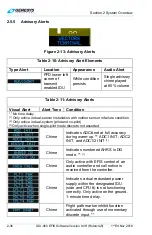
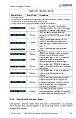
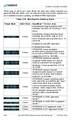
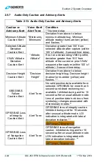
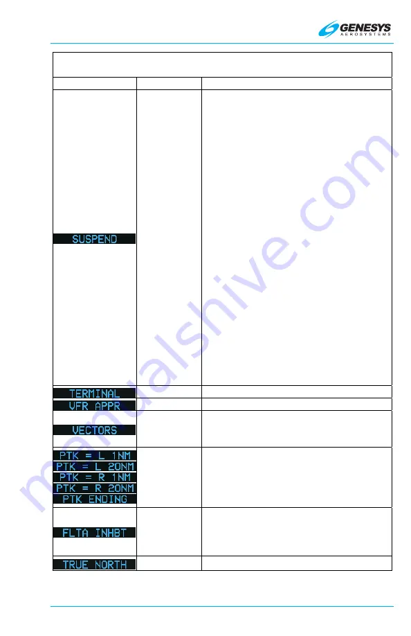
Table 2-12: Side-Specific Advisory Alerts 

Visual Alert 

Alert Tone  Condition 

** No time delay


Chime 

Automatic waypoint sequencing is 
suspended under any of the following 
conditions: 
1)  Pilot has selected a manual 

GPS/SBAS OBS. 

2)  Active waypoint is the missed 

approach waypoint, and missed 
approach procedure has not been 
armed (ARM) nor initiated (MISS). 

3)  Aircraft is in a published or 

manually created holding pattern, 
and pilot has not chosen to 
continue (CONT) out of the 
holding pattern. 

4)  Leg following active waypoint is a 

manual termination leg, and the 
pilot has not chosen to resume 
(RESUME) to the waypoint 
following the manual termination.  

5)  The aircraft is in a repeating SAR 

pattern (see SAR appendix), and 
the pilot has not chosen to 
continue out of SAR pattern.** 

Chime 

GPS/SBAS in terminal mode. ** 

Chime 

GPS/SBAS in VFR approach mode. ** 

Chime 

GPS/SBAS in vectors to final 
approach mode prior to sequencing 
FAWP. ** 

Chime 

GPS/SBAS parallel offset path 
advisory. ## is nautical miles left (L) or 
right (R) of main path. PTK ENDING if 
within the parallel offset distance from 
a parallel offset exit waypoint. ** 

Chime 

Shown when FLTA function is 
automatically inhibited during normal 
operation. TAWS INHBT advisory has 
priority. ** 

Chime 

System operating in true north mode.** 


Summary of Contents for IDU-450 8.0H

Page 1: ...IDU 450 EFIS Software Version 8 0H Rotorcraft IDU 450 8 0H Rotorcraft Pilot Guide PRECISE PERFORMANCE PROVEN EXPERIENCE PERSONALIZED ATTENTION...

Page 2: ...e ground tests limitations and emergency procedures 2019 Genesys Aerosystems All Rights Reserved No part of this document may be reproduced in any form or by any means without prior written consent of...

Page 3: ...chmidt Rev A Fixed footer in Section 5 to read 8 0H instead of 8 0F Title page Changed copyright to 2019 and changed footer to reflect Rev A Apr 2019 Back cover changed to reflect 2019 Apr 2019 G Schm...

Page 4: ...ventions 2 20 2 5 Warning Caution Advisory System 2 21 2 5 1 Time Critical Warning and Caution Alerts 2 22 2 5 2 Warning Alerts 2 25 2 5 3 Caution Alerts 2 27 2 5 4 Side Specific Caution Alerts 2 35 2...

Page 5: ...3 3 4 Analog AGL Indication 3 10 3 3 5 Decision Height 3 11 3 3 6 Airspeed Display 3 11 3 3 7 Airspeed Display With EFIS Coupled 3 13 3 3 8 Heading Display 3 13 3 3 9 Pitch Scale 3 15 3 3 10 Turn Rate...

Page 6: ...e ND Boundary Circle Symbol 3 41 3 4 4 Clock Options 3 42 3 4 5 Air Data and Groundspeed 3 42 3 4 6 Fuel Totalizer Waypoint Distance Functions 3 43 3 4 7 Navigation Data 3 44 3 4 8 Analog Navigation S...

Page 7: ...Arrival Column 3 64 3 6 9 Fuel Remaining Column 3 64 3 7 Hover Page 3 65 3 7 1 Hover Page Screen Range 3 65 3 7 2 Hover Vector 3 65 3 7 3 Compass Rose Symbols 3 66 3 7 4 Active Flight Plan Path Manual...

Page 8: ...and Step By Step Procedures 5 1 5 1 Menu Functions 5 1 5 1 1 Menu Philosophy 5 2 5 1 2 Avoidance of Autonomous Behavior 5 2 5 2 Menu Synchronization 5 3 5 3 Menu Function Types 5 5 5 4 Top Level Menu...

Page 9: ...Only Step By Step 5 20 5 7 16 RAIM Prediction 5 21 5 8 Active Flight Plan ACTV Menu 5 23 5 8 1 Main Menu 5 23 5 8 2 Active Flight Plan ACTV Menu Options 5 24 5 8 3 Active Flight Plan ACTV Menu Options...

Page 10: ...22 MFD Page PAGE Menu 5 51 5 22 1 MFD Page PAGE Menu Step By Step 5 52 5 23 MFD NAV Log Page Step By Step 5 52 5 24 MFD HSI Page Step by Step 5 53 5 24 1 MFD HSI Declutter DCLTR Menu 5 53 5 25 MFD ND...

Page 11: ...5 Selection of an Instrument Procedure 7 35 7 15 1 Missed Approach and Departure Path Definition 7 35 7 15 2 Standard Instrument Departure DP Step By Step 7 37 7 15 3 Standard Terminal Arrival Route S...

Page 12: ...xcessive Downward Deviation from an ILS Glideslope GPWS Mode 5 8 12 8 9 External Sensors and Switches 8 13 8 10 TAWS Basic Parameter Determination 8 15 8 11 TAWS Automatic Inhibit Functions Normal Ope...

Page 13: ...tations 9 9 9 19 Certification Basis 9 10 9 20 Environmental Requirements 9 11 T 1 Traffic Page Access T 1 T 2 Menu Declutter T 1 T 3 Traffic Symbology T 2 T 3 2 Traffic Display Definitions T 3 T 3 3...

Page 14: ...2 Ownship Symbol D 4 D 2 3 Datalink Page Legend D 4 D 2 4 Air Data and Groundspeed D 4 D 2 5 Clock and Options D 4 D 2 6 Datalink Page Screen Range D 6 D 2 7 Boundary Circle Symbols D 7 D 2 8 Active...

Page 15: ...RD 7 Turn Rate Indicator RD 7 RD 8 RED X Invalid Input RD 7 SAR 1 Search and Rescue SAR Patterns SAR 1 SAR 1 1 SAR Pattern Step by Step Procedures SAR 1 SAR 2 Expanding Square Pattern SAR 4 SAR 3 Risi...

Page 16: ...26 TABLE 2 6 WARNING ALERTS 2 26 FIGURE 2 12 CAUTION ALERTS 2 27 TABLE 2 7 CAUTION ALERT ELEMENTS 2 27 TABLE 2 8 CAUTION ALERTS 2 27 TABLE 2 9 SIDE SPECIFIC CAUTION ALERTS 2 35 FIGURE 2 13 ADVISORY A...

Page 17: ...CATOR 3 14 FIGURE 3 30 DISPLACED HEADING BUG 3 14 TABLE 3 7 HEADING DISPLAY 3 15 FIGURE 3 31 PITCH SCALE 3 15 FIGURE 3 32 PITCH SCALE ZENITH AND NADIR SYMBOLS 3 16 FIGURE 3 33 TURN RATE INDICATOR 3 16...

Page 18: ...APPROACH 3 40 FIGURE 3 67 NORTH UP ARC MODE 3 40 FIGURE 3 68 NORTH UP CENTERED MODE 3 41 FIGURE 3 69 HEADING UP CENTERED MODE 3 41 FIGURE 3 70 COMPASS ROSE ND BOUNDARY CIRCLE SYMBOL 3 41 TABLE 3 14 C...

Page 19: ...FIGURE 3 104 HOVER VECTOR SYMBOLOGY 3 66 FIGURE 3 105 HOVER VECTOR COMPASS ROSE 3 66 FIGURE 3 106 HOVER VECTOR ACTIVE FLIGHT PLAN PATH MANUAL COURSE 3 67 FIGURE 3 107 HOVER VECTOR ACTIVE FLIGHT PLAN...

Page 20: ...RE 5 1 IDU 450 INPUT CONTROLS 5 1 TABLE 5 1 ENCODER FUNCTIONS FOR ALL PAGES 5 1 FIGURE 5 2 IDU 450 INPUT CONTROLS 5 2 TABLE 5 2 MENU SYNCHRONIZATION 5 3 FIGURE 5 3 PFD TOP LEVEL MENU 5 5 TABLE 5 3 TOP...

Page 21: ...TABLE 7 5 LEG SEGMENTS FOR PATHS CONSTRUCTED BY THE EFIS 7 18 FIGURE 7 10 UNNAMED WAYPOINTS 7 21 FIGURE 7 11 PARALLEL OFFSET PTK PTK ENTRY 7 24 FIGURE 7 12 PARALLEL OFFSET PTK PTK ENDING 7 25 TABLE 7...

Page 22: ...GURE 8 10 ROTORCRAFT GPWS MODE 4 8 12 TABLE 8 10 HTAWS GPWS MODE 5 ENVELOPES 8 13 FIGURE 8 11 ROTORCRAFT GPWS MODE 5 8 13 TABLE 8 11 EXTERNAL SENSORS AND SWITCHES APPLICABLE TAWS 8 14 TABLE 8 12 HTAWS...

Page 23: ...AYPOINT DISTANCE FUNCTIONS S 4 FIGURE S 7 MFD STRIKES FORMAT FORMAT MENU S 5 TABLE S 3 MENU SYNCHRONIZATION S 5 FIGURE D 1 DATALINK SYMBOLOGY WITH G METAR ON D 1 FIGURE D 2 DATALINK SYMBOLOGY WITH NEX...

Page 24: ...UARE PATTERN INDIVIDUAL LEG SELECTED SAR 5 FIGURE SAR 5 RISING LADDER PATTERN SAR 5 FIGURE SAR 6 RISING LADDER PATTERN PARAMETERS SAR 6 TABLE SAR 2 RISING LADDER PATTERN PARAMETERS SAR 6 FIGURE SAR 7...

Page 25: ...th HUD symbology overlaying real time 3 D virtual view of the outside world This synthetic vision provides the pilot in IMC with simple visual clues for navigation and aircraft control as those used i...

Page 26: ...g may be controlled locally or remotely with a default state being with the local control NOTE If entering ground maintenance mode with bright light shining or reflecting directly into the display shi...

Page 27: ...kly gain familiarity with where to locate controls to manipulate the system for each operation IFR PROCEDURES Section 7 Detailed information and instruction about selecting and flying instrument proce...

Page 28: ...troduction 1 4 IDU 450 EFIS Software Version 8 0H Rotorcraft 1st Ed Nov 2018 INDEX Alphabetical listing of terms or keywords with corresponding page numbers GLOSSARY Alphabetical listing of definition...

Page 29: ...ght Manual AGL Above Ground Level AHRS Attitude Heading Reference System AIRAC Aeronautical Information Regulation and Control AIRMET Airmen s Meteorological Information ALT Pressure Altitude ALT SEL...

Page 30: ...r Clockwise CDA Continuous Descent Approach CDI Course Deviation Indicator CF Course to Fix ARINC 424 Leg CI Course to Intercept ARINC 424 Leg CLR Clear CNX Cancel COM Communication CONT Continue CPLT...

Page 31: ...avigation Overlay Service EGPWS Enhanced Ground Proximity Warning System EQPMNT Equipment ESSNTL Essential ETA Estimated Time of Arrival ETE Estimated Time Enroute ETT EFIS Training Tool EXCD Exceedan...

Page 32: ...ion FSD Full Scale Deflection FT Feet FTE Flight Technical Error FTP Fictitious Threshold Point FNCT Function GAGAN India s GPS and GEO Augmented Navigation System GARP GNSS Azimuth Reference Point GB...

Page 33: ...ontal Protection Level HRZ SYNC Horizon Synchronization HSI Horizontal Situation Indicator HUD Head Up Display IAP Instrument Approach Procedure Initial Approach Point IAS Indicated Airspeed IAWP Init...

Page 34: ...ing 100 or visibility 1 mile LNAV Lateral Navigation LOC Localizer LOI Loss of Integrity LON Loss of Navigation Longitude LP Localizer Performance LPV Localizer Performance with Vertical Guidance LTP...

Page 35: ...stance ND Navigation Display NDB Nondirectional Beacon NEXRAD Next Generation Radar network of weather radars operated by the National Weather Service NWS also NXRD NIMA National Imagery and Mapping A...

Page 36: ...ssure altitude readout QNH Altimeter setting provides MSL altitude at a reporting point RA Resolution Advisory Traffic Function RADALT Radar Altimeter also RALT RAD DST Radial and Distance RAIM Receiv...

Page 37: ...Stand by STD Standard STRKS Strikes Lightning detection SVS Synthetic Vision System SYMB Symbol SYNC Synchronize SYRD System Requirements Document TA Traffic Advisory Traffic Function TACAN Ultra Hig...

Page 38: ...l VAL Vertical Alert Limit VAPP Target approach airspeed VD Heading to DME Distance ARINC 424 Leg VDI Vertical Deviation Indicator VERT Vertical VFE Maximum flap extended speed VFOM Vertical Figure of...

Page 39: ...sitive rate of climb with one engine inoperative WAAS Wide Area Augmentation System WGS84 World Geodetic System 1984 WPT Waypoint WX Weather XFILL Crossfill 2 2 System Overview Figure 2 1 IDU 450 Prim...

Page 40: ...the respective MFD becomes transmit enabled Figure 2 2 IDU 450 Multifunction Flight Display 2 2 1 Functional Integration and Display Redundancy Pilot Co Pilot IDU 1 IDU 2 IDU 3 IDU 4 GPS 1 GPS 2 ADC 1...

Page 41: ...3 depicts a typical architecture used by IDUs The IDUs depend upon intra system between IDUs on a side depicted as Sync and inter system between IDUs on opposite sides depicted as Crosslink to achiev...

Page 42: ...rior to the last system shutdown are read for a good system initialization even if system sensors are failed or not yet initialized For future updates i e updating software version 8 0H to 8 0J all ai...

Page 43: ...k is initialized to on Map modes are set to allowed values If configured the magnetic variation coefficients database is read from the flash drive storage and CRC 32 checked The IDU decides whether it...

Page 44: ...imits the system auto sets the altimeter based on the terrain elevation at the startup point only applicable at surveyed airports In case of QFE mode operation the application will autoset the altimet...

Page 45: ...ensors are in normal condition Display screens initialize as follows a IDU 1 PFD screen b Other IDUs IDU 2 initializes to MFD screen All other IDUs initialize to MFD screen c On IDU 0 2 3 or 4 with fu...

Page 46: ...tically acknowledged for 5 seconds to reduce nuisance alerting NOTE Intra system and inter system synchronization messages are paused when any IDU menu is active After IDU initialization if any menu i...

Page 47: ...on the same side is referred to as intra system communications In a dual system pilot and co pilot configuration the crosslink side to side communications is referred to as inter system communications...

Page 48: ...Any color representation may not be identical as it appears on the IDU WHITE for items set by pilot and held by the EFIS or items where device feedback is not expected marker beacon receiver high low...

Page 49: ...s shades shows terrain within 2000 and below aircraft altitude BROWN in a variety of shades indicates earth terrain portion of PFD or when above 100 feet less than aircraft altitude on MFD BLUE in a v...

Page 50: ...ged the flashing behavior stops the audible alert is interrupted and the discrete outputs are deactivated 2 5 1 Time Critical Warning and Caution Alerts Time critical warning and caution alerts trigge...

Page 51: ...Plays only once Table 2 4 Time Critical Warning and Caution Alerts Visual Alert Voice Alert No Voice Alert Condition No time delay Warning Obstruction Warning Obstruction Obstruction within TAWS FLTA...

Page 52: ...2 second time delay Caution Terrain Caution Terrain Within GPWS Mode 2 caution Terrain cell within TAWS FLTA caution envelope Half second time delay Sink Rate Sink Rate Within GPWS Mode 1 caution enve...

Page 53: ...aution but instead is a pilot selection annunciation Time critical warning and caution alerts are prioritized so only one alert at a time is active GPWS Mode 1 Warning GPWS Mode 2 Warning TAWS FLTA Wa...

Page 54: ...ow its low fuel warning threshold 3 Total aircraft fuel is below the pilot set emergency fuel threshold 1 minute time delay Warning Obstruction Warning Obstruction Obstruction within TAWS FLTA warning...

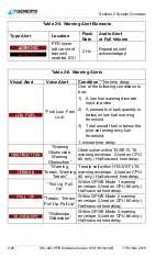
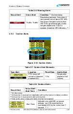
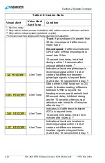
Page 55: ...rts Figure 2 12 Caution Alerts Table 2 7 Caution Alert Elements Type Alert Location Flash Rate Audio Alert PFD lower left corner of transmit enabled IDU 1 Hz Single alert played at full volume Table 2...

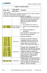
Page 56: ...o set by audio radio interface with NGT 9000R transponder 2 second time delay Alert Tone Indicates no valid bank pitch nor heading received from enumerated AHRS s for more than 1 second Inhibited duri...

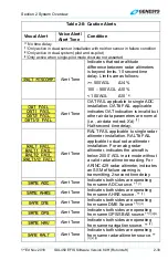
Page 57: ...s used by displays on the indicated side exceed miscompare thresholds Compares the following critical parameters 1 Attitude pitch and roll 2 Heading 3 Pressure altitude 4 Indicated airspeed 5 Localize...

Page 58: ...t if on a missed approach or 3 along route distance to destination Not activated in climbing flight nor if below 60 kts groundspeed 5 minute time delay Alert Tone Indicates personality module for desi...

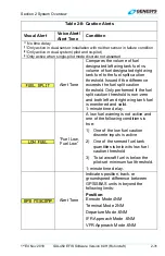
Page 59: ...ifference exceeds the fuel split caution threshold Only performed if the fuel split caution threshold is non zero and both left and right wing tank fuel is monitored and valid 1 minute time delay Fuel...

Page 60: ...econds after unusual attitude mode 1 Alert Tone Indicates at least one glideslope is receiving a signal within 1 dot of center and difference between glideslope signals is beyond limits 0 25 dots 10 s...

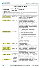
Page 61: ...ta parameters are normal i e air data not red X d 1 Half second time delay Alert Tone RALT FAIL applicable to single radar altimeter installation RALT FAIL applicable to dual radar altimeter installat...

Page 62: ...calculation Issued if the difference exceeds the totalizer mismatch caution threshold Only performed if 1 Totalizer mismatch caution threshold is non zero 2 Fuel totalizer is enabled 3 Unmonitored fue...

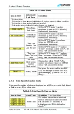
Page 63: ...Half second time delay Within GPWS Mode 4 1 Too Low Terrain envelope Used on CPU 0 only Half second time delay Too Low Gear Too Low Gear Within GPWS Mode 4 2 Too Low Gear envelope Used on CPU 0 only H...

Page 64: ...ion with neither sensor in failure condition 2 Only active in dual system pilot and co pilot 3 Only active when single pilot mode discrete not asserted Chime Indicates ADC not at full accuracy during...

Page 65: ...inhibited through discrete input Chime TAWS low altitude mode activated through use of discrete input Chime Only active with TCAS II Indicates system is either in standby or executing functional test...

Page 66: ...tion 2 second time delay Chime GPS SBAS actual navigation performance in nautical miles based upon current GPS SBAS HPL Value ranges from 0 01 to 15 0 NM Chime GPS SBAS automatic required navigation p...

Page 67: ...ttern 4 Leg following active waypoint is a manual termination leg and the pilot has not chosen to resume RESUME to the waypoint following the manual termination 5 The aircraft is in a repeating SAR pa...

Page 68: ...r capture within 100 of altitude 2 second time delay Decision Height Caution Alert Decision Height Deviation from above to below decision height bug Decision height readout turns amber yellow and flas...

Page 69: ...ssage is immediately muted by activating the warning caution acknowledge switch 2 5 9 Visual Alert Prioritization and Declutter Visual alerts are visually prioritized so warnings are displayed above c...

Page 70: ...ii Puerto Rico Bahamas Bermuda Mexico Central and South America International All available coverage except North and South America World Major airports and navigation with the Americas The updateable...

Page 71: ...order for each approach is retrievable as a procedure select the procedure by name to load the appropriate waypoints and legs into the flight plan Waypoints utilized as a final approach waypoint FAWP...

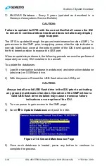
Page 72: ...on to expose the USB port When an update is performed the following procedures must be performed separately on every IDU installed in the aircraft To update the databases 1 Load the navigation databas...

Page 73: ...monstration application to fly anywhere in the world while performing any procedure except takeoff and landing based on the current navigation database Use this feature on the ground in ground mode as...

Page 74: ...es as a multi purpose tool for training pilots and provides features to record and capture images See user guide distributed with the ETT installer for further details 2 9 Application Software Air Mod...

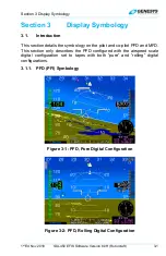
Page 75: ...This section details the symbology on the pilot and co pilot PFD and MFD This section only describes the PFD configured with the airspeed scale digital configuration set to tapes with both pure and ro...

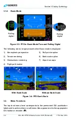
Page 76: ...1 Atmospheric perspective 2 Terrain rendering 3 Obstructions rendering 4 Flight path marker 5 Roll pointer option 6 Bank scale option 7 Airport runways With Bank Scale Without Bank Scale Figure 3 4 PF...

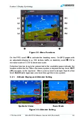
Page 77: ...to increase scale or CCW to decrease scale Selection lists too long to be presented in the available space indicate the location within the list When the menu system is beyond the top level EXIT R1 e...

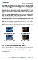
Page 78: ...setting is selected no mode is annunciated below the altimeter setting QFE Barometric setting resulting in the altimeter displaying height above a reference elevation e g airport or runway threshold...

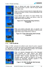
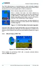
Page 79: ...ting annunciation is white and the target altitude bug is filled white at all times Figure 3 9 Target Altitude Bug Not Vertically Integrated 3 2 3 VNAV Sub Mode When in VNAV sub mode the altitude scal...

Page 80: ...ld capture VNAV altitude bug setting annunciation is green and flashes while the VNAV altitude bug is filled magenta When in a climb or descent mode the VNAV altitude bug setting annunciation is white...

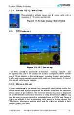
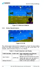
Page 81: ...luding terrain obstructions traffic and runways are presented conformally as if seen directly in front of the aircraft while looking outside 3 3 1 Minimum Altitude A user settable minimum altitude bug...

Page 82: ...m format providing analog and digital representation of VSI in feet per minute fpm For example rate of descent in Figure 3 16 is 700 fpm Table 3 1 Scale Graduations and Display Traffic Installed Scale...

Page 83: ...scent mode Otherwise the VSI bug setting is white and VSI bug is hollow white Figure 3 18 VSI Bug Vertically Integrated When not vertically integrated with an autopilot the VSI bug setting annunciatio...

Page 84: ...rner of the PFD above the active waypoint identifier with a green circular tape and digital readout in the center The circular tape has a radial line at its end and disappears above 1000 AGL Figure 3...

Page 85: ...bbreviation DH and by a yellow radial on the analog indicator When the aircraft descends below decision height DH turns amber yellow and flashes and the circular tape turns amber yellow This is accomp...

Page 86: ...ormat to provide analog representation of IAS achieved in five seconds assuming the instantaneous longitudinal acceleration is maintained Figure 3 23 Airspeed Trend The airspeed scale for Part 27 and...

Page 87: ...climb or descent mode otherwise white Airspeed Bug Filled white at all times Filled white when in airspeed climb or descent mode otherwise hollow white 3 3 7 Airspeed Display With EFIS Coupled Airspee...

Page 88: ...w the heading pointer that moves left and right to indicate the lateral acceleration sensed by the AHRS in the same manner as the ball in a mechanical slip indicator The integral slip indicator is res...

Page 89: ...far left limit of the heading scale to indicate the shortest not necessarily the safest direction of turn to the active waypoint Figure 3 30 The waypoint pointer and shortest direction of turn indica...

Page 90: ...background Pointer bars at the ends of each major increment indicate direction to the horizon and automatically declutter to present the fewest possible increments needed to unambiguously display pitc...

Page 91: ...Less than 30 pitch up More than 30 pitch up Figure 3 35 Unusual Attitude Mode The following features are disabled in unusual attitude mode 1 Terrain and obstruction rendering 2 CDI 3 VDI 4 Flight pat...

Page 92: ...ns Terrain and obstruction rendering uses hidden surface removal technique s while terrain sky rendering uses atmospheric perspective techniques Terrain with obstruction rendering is collectively pilo...

Page 93: ...o 46 24 arc seconds 46 to 62 48 arc seconds 46 45 62 to 70 72 arc seconds 62 61 70 to 74 96 arc seconds 70 69 74 to 75 120 arc seconds 74 73 Table 3 9 Terrain and Obstruction Rendering Levels Feature...

Page 94: ...HED NAVIGATIONAL INSTRUMENT PROCEDURES AND NAVIGATIONAL CHARTS IN ALL FLIGHT CONDITIONS When terrain and obstruction rendering is deselected or disabled the PFD background is a conventional blue over...

Page 95: ...and size and only shown in conjunction with terrain regardless of altitude Obstructions representing a collision hazard are annunciated aurally and with a caution or warning flag See Section 2 System...

Page 96: ...rtically displaced perpendicular to the horizon to account for aircraft climb or descent angle Because the FPM is used in conjunction with a 3 D background the FPM utility normally associated with a H...

Page 97: ...t disappears to allow the pilot to concentrate on the large aircraft symbol reference marks for unusual attitude recovery FPM at low speed airspeed 45 KIAS behavior further depends upon whether or not...

Page 98: ...s an inner concentric ring indicating 10 knots groundspeed an outer concentric ring indicating 20 knots groundspeed and a vertical and horizontal dashed line passing through the center extending to th...

Page 99: ...mbology with Hover page selected on MFD NOTE In the event the bank scale was decluttered it becomes uncluttered while at low speed 30 knots groundspeed 3 3 16 Bank Angle Scale The bank scale and roll...

Page 100: ...ation receiver are displayed on the PFD and disabled when the selected NAV source is FMS Valid marker beacon signals cause circular indicators with appropriate coloring and markings to display in the...

Page 101: ...2 Dual Cue Figure 3 49 Flight Director FD1 Single Cue FD2 Dual Cue Figure 3 50 Flight Director Basic Mode 3 3 21 Course Deviation Indicator CDI Without Autopilot With Autopilot Figure 3 51 Course Devi...

Page 102: ...inal and various approach modes according to the Level of Service record Table 3 10 CDI Behavior and Color CDI Pointer and Condition Color or Behavior Full Scale Deflection Flash Slaved to GPS SBAS Sc...

Page 103: ...nsing Lateral deviations in failed state Red X displayed over CDI EFIS not coupled with autopilot Selected NAV source FMS2 Selected NAV source VOR1 Selected NAV source VOR2 EFIS coupled system with au...

Page 104: ...HDG BUG Heading Bug Sub Mode Guidance 4 HDG Failure Sub Mode 3 3 24 Heading Bug Sub Mode The heading bug sub mode is active when selected through the menu system and commands roll angles to track the...

Page 105: ...bove the top left corner of the CDI scale The heading roll steering sub mode annunciation does not appear as it is not required with autopilot mode annunciations or when an installation does not inclu...

Page 106: ...Glideslope Source must be valid when a valid glideslope is received Cyan LPV or VNAV mode Source is valid if On VNAV descent segments when approaching the Top of Descent point so as to provide descent...

Page 107: ...ft LPV VNV G During GPS LON or GPS VLON Pointer and Text Color Amber Yellow Figure 3 56 VDI Color during GPS SBAS LON or VLON 3 3 27 Vertical Deviation Indicator EFIS Coupled Figure 3 57 EFIS Coupled...

Page 108: ...active navigation route or manual OBS course in 3 D with a series of skyway boxes which overly the flight plan route at a desired altitude and provide lateral and vertical guidance See Section 7 IFR P...

Page 109: ...distance to the waypoint are displayed in the lower right corner of the PFD in magenta If a target altitude is not set and the active waypoint has a VNAV altitude associated as in Figure 3 55 the ide...

Page 110: ...GPS SBAS LON Ownship Symbol Figure 3 63 White Mutually exclusive with analog AGL and traffic thumbnail Mini Map disappears in Unusual Attitude Mode 3 3 31 Runways The PFD displays airport runways in...

Page 111: ...defined in Table 3 13 Table 3 13 Runway Drawing Criteria Feature Color Notes Runway markings aiming point markings centerline designation and displaced threshold arrows Dark gray According to characte...

Page 112: ...3 4 MFD Symbology Navigation display ND may be configured the following formats 1 Moving Map 2 Conventional HSI 3 Navigation Log 4 Strikes see WX 500 Lightning Strikes Appendix 5 Traffic see Traffic...

Page 113: ...are Version 8 0H Rotorcraft 3 39 3 4 2 Moving Map Figure 3 64 Basic Moving Map NOTE When selected latitude longitude is displayed below the ownship symbol as aircraft current position Figure 3 65 Lati...

Page 114: ...Section 3 Display Symbology 3 40 IDU 450 EFIS Software Version 8 0H Rotorcraft 1st Ed Nov 2018 Figure 3 66 Moving Map with Instrument Approach Figure 3 67 North Up Arc Mode...

Page 115: ...igure 3 68 North Up Centered Mode Figure 3 69 Heading Up Centered Mode 3 4 3 Compass Rose ND Boundary Circle Symbol In heading up mode the magnetic digital heading readout and pointer are aligned with...

Page 116: ...ter mode Manual declutter mode Terrain Status Enabled or Disabled Terrain status is indicated by the absence or presence of terrain Traffic Status See Traffic appendix WX 500 Status See Strikes append...

Page 117: ...3 International Standard Atmosphere ISA Difference between ISA temperature and current outside air temperature is displayed digitally in C or F negative values less than standard OAT Decluttered if th...

Page 118: ...e and time are based on a direct geodetic path Waypoint information is white but turns amber yellow with GPS LON caution ETA or ETE Degree or True North T symbol Range Based on instantaneous fuel flow...

Page 119: ...djusted threshold needed to achieve desired symbol count are always shown IFR airports that are not large airports are shown in levels 1 2 3 and 4 and VFR airports are shown in levels 1 2 and 3 2 VORs...

Page 120: ...ingle pixel solid lines Within 500 Triple pixel solid lines Within airspace vertical limits Color of Airspace Class C control area TRSAs Class D Green Class B TCAs where applicable Blue Caution danger...

Page 121: ...an for VOR1 green for VOR2 If the DME channel is in hold mode the associated distance readout is amber yellow and the letter H is shown above the distance readout Figure 3 96 The size of the HSI depen...

Page 122: ...ilot selectable to declutter the display by deselecting terrain independent declutter of obstructions is not possible Furthermore terrain and obstruction rendering is disabled when 1 The GPS SBAS sens...

Page 123: ...n shades FLTA alerts Amber and Red See Section 8 TAWS Water at all altitudes Deep Blue Takes precedence over other colors Obstructions are displayed on the ND in correct relationship to the ownship sy...

Page 124: ...point pointer analog navigation symbology and field of view lines are removed from the display Figure 3 81 shows the line with bearing and distance from the map center to the aircraft s current positi...

Page 125: ...a Direct To leg DME distance or DME terminations INT intercept terminations RAD radial terminations Figure 3 83 Direct Point 3 4 14 Altitude Capture Predictor Top of Descent Top of Descent Top of Cli...

Page 126: ...and matches the lateral navigation guidance given on the PFD GPS SBAS CDI in automatic OBS mode skyway boxes and mini map The fly over waypoint symbol is distinct from fly by waypoints and consists of...

Page 127: ...flight plan and GPS SBAS OBS setting is automatic the flight plan path is shown on the ND in correct relationship to the ownship symbol See Section 5 Menu Functions and Procedures for details on crea...

Page 128: ...m Off Narrow FOV Zoom On Figure 3 88 Field of View 3 4 18 Range The white range ring is centered on the aircraft s position to quickly estimate distances Distance in NM from the aircraft to the ring i...

Page 129: ...l deviation indicator and a TO FROM indicator VOR1 VOR2 and ADF navigation are displayed with a magenta single line FMS1 a cyan single line VOR1 needle and a green double line VOR2 needle and ADF tune...

Page 130: ...e 2 VNV2 B Default FMS barometric VNAV mode 3 GS1 Glideslope 1 4 GS2 Glideslope 2 3 5 1 Conventional HSI PTR Format When selected the ND displays conventional HSI symbology including a selected course...

Page 131: ...I PTR Format HSI with VDI and Glideslope When VOR1 and VOR2 pointers are selected for display a distance display at the bottom of the ND appear If bearing or distance is not valid the respective field...

Page 132: ...elected VOR pointers appears at the bottom of the display in the same color of the respective pointer When an ADF2 is enabled the ADF2 double needle is as shown in Figure 3 95 Figure 3 94 Analog Navig...

Page 133: ...r Beacon Displayed 3 5 3 Compass Rose Symbols When selected a digital heading readout and pointer aligned with the longitudinal axis of the ownship symbol appear on the compass rose boundary circle No...

Page 134: ...ion 7 IFR Procedures for description of the following heading modes with the AHRS and EFIS 1 ADAHRS Slaved EFIS Magnetic North 2 ADAHRS Slaved EFIS True North 3 ADAHRS Free DG EFIS Magnetic North 4 AD...

Page 135: ...layed in the upper left corner of the NAV Log 1 Zulu or LCL Time As specified in 3 4 4 2 Groundspeed Displayed digitally in knots 3 6 2 Fuel Remaining and Fuel Flow Data The following are displayed in...

Page 136: ...approach segment 6 VFR Waypoint is part of a VFR approach 7 STAR Waypoint is part of a standard terminal arrival procedure 8 DP Waypoint is part of a Departure Procedure 9 PTK Parallel Offset In the c...

Page 137: ...turn either left or right turns as well as the entry and exit course for the procedure turn 8 Holding patterns are shown with a pictorial representation of a holding pattern either left or right turn...

Page 138: ...the leg between waypoints 3 6 8 Estimated Time of Arrival Column ETA at the active waypoint and all subsequent waypoints are displayed immediately to the right of the ETE column ETA at the active wayp...

Page 139: ...Figure 3 103 Hover Page Orientation 3 7 1 Hover Page Screen Range The following selectable hover page screen ranges are available all distances are from the ownship symbol to the compass rose 400 800...

Page 140: ...ology The ownship symbol indicates 0 knots groundspeed and a dot connected to the ownship symbol by a gray line floating over the hover page to indicate flight direction and groundspeed Deviation of t...

Page 141: ...path meets all the requirements of GPS SBAS path definition and matches the lateral navigation guidance given on the PFD GPS SBAS CDI in automatic OBS mode skyway boxes and mini map Active flight plan...

Page 142: ...s and some heliports in correct relationship and scale to the ownship symbol Immediately upon a system startup on the ground the runways for the nearest airport are displayed Upon activation of a DP V...

Page 143: ...Displayed as specified in 3 4 5 3 7 8 Clock Displayed as specified in 3 4 4 3 7 9 AGL Indication Above 2 500 AGL 2 500 AGL 500 AGL 200 AGL Figure 3 109 Hover Vector AGL Indication AGL altitude is dis...

Page 144: ...f column has a widened area for better registration against the scale accordingly so the widened area disappears at AGL altitudes greater than 1 000 feet i e maximum analog indication Scaling 0 to 100...

Page 145: ...led and AHRS normal Mode 5 GPS SBAS and AHRS failed and ADC normal Mode 6 ADC and AHRS failed and GPS SBAS normal Mode 7 GPS ADC and AHRS failed To use this section review the following table and note...

Page 146: ...nway OK 1 25 Waypoint Pointer 7 1 7 7 7 Heading Scale 7 7 7 7 7 7 AGL Ind OK 2 4 OK 11 11 4 Flight Path Marker OK 1 14 Hover Vector OK Ground Track 7 1 7 7 7 Heading Indicator 7 7 7 7 Horizon OK OK OK...

Page 147: ...OK OK Wind 21 3 WX 500 Data OK OK OK OK OK OK OK OK Compass Rose 9 9 9 9 9 9 Fuel Totalizer Functions 23 24 23 23 12 12 12 12 True Airspeed OK OK OK OK Density Altitude OK OK OK OK OAT ISA Display OK...

Page 148: ...ing scale aligned with aircraft track and heading indication is removed In heading only failure mode or AHRS failure mode combined with GPS failure heading scale is replaced with a red X Note 9 In hea...

Page 149: ...ions specified in TAWS automatic inhibit function abnormal operation 4 1 1 Oat Sensor Failure Mode The EFIS has an OAT sensor failure mode With the OAT sensor failed wind OAT density altitude and true...

Page 150: ...ght currently in Position is still presented based upon a GPS navigation solution 3 Loss of Navigation displayed with no time delay of the onset of the following a The absence of power b Equipment mal...

Page 151: ...t be calculated a dead reckoning solution is provided with a timer This solution is calculated from heading and TAS derived from the AHRS and ADC 2 Loss of Vertical Navigation Figure 4 4 Loss of Verti...

Page 152: ...ior to sequencing the FAWP HAL should be 0 3 NM with no limit on VAL ii After sequencing the FAWP HAL 556m 0 3NM and VAL 50m When in LNAV mode the fault detection function detects positioning failures...

Page 153: ...ov 2018 IDU 450 EFIS Software Version 8 0H Rotorcraft 4 9 4 3 PFD Failure Mode 0 Figure 4 5 PFD Failure Mode 0 GPS ADC and AHRS Normal 4 3 1 MFD Failure Mode 0 Normal Mode Figure 4 6 MFD Failure Mode...

Page 154: ...450 EFIS Software Version 8 0H Rotorcraft 1st Ed Nov 2018 4 4 PFD Failure Mode 1 Figure 4 7 PFD Failure Mode 1 GPS SBAS Failed ADC and AHRS Normal 4 4 1 MFD Failure Mode 1 Figure 4 8 MFD Failure Mode...

Page 155: ...50 EFIS Software Version 8 0H Rotorcraft 4 11 4 5 PFD Failure Mode 2 Normal Mode Figure 4 9 PFD Failure Mode 2 Normal Mode ADC Failed GPS SBAS and AHRS Normal 4 5 1 MFD Failure Mode 2 Figure 4 10 MFD...

Page 156: ...50 EFIS Software Version 8 0H Rotorcraft 1st Ed Nov 2018 4 6 PFD Failure Mode 3 Figure 4 11 PFD Failure Mode 3 AHRS Failed GPS SBAS and ADC Normal 4 6 1 MFD Failure Mode 3 Figure 4 12 MFD Failure Mode...

Page 157: ...2018 IDU 450 EFIS Software Version 8 0H Rotorcraft 4 13 4 7 PFD Failure Mode 4 Figure 4 13 PFD Failure Mode 4 GPS SBAS and ADC Failed AHRS Normal 4 7 1 MFD Failure Mode 4 Figure 4 14 MFD Failure Mode...

Page 158: ...50 EFIS Software Version 8 0H Rotorcraft 1st Ed Nov 2018 4 8 PFD Failure Mode 5 Figure 4 15 PFD Failure Mode 5 GPS SBAS and AHRS Failed ADC Normal 4 8 1 MFD Failure Mode 5 Figure 4 16 MFD Failure Mode...

Page 159: ...2018 IDU 450 EFIS Software Version 8 0H Rotorcraft 4 15 4 9 PFD Failure Mode 6 Figure 4 17 PFD Failure Mode 6 ADC and AHRS Failed GPS SBAS Normal 4 9 1 MFD Failure Mode 6 Figure 4 18 MFD Failure Mode...

Page 160: ...IDU 450 EFIS Software Version 8 0H Rotorcraft 1st Ed Nov 2018 4 10 PFD Failure Mode 7 Figure 4 19 PFD Failure Mode 7 GPS SBAS ADC and AHRS Failed 4 10 1 MFD Failure Mode 7 Figure 4 20 MFD Failure Mod...

Page 161: ...n Soft menu function tiles appear next to the appropriate IDU button and the right encoder when appropriate On the PFD scroll to activate the heading menu On MFD pages with an adjustable display e g N...

Page 162: ...to be presented in the space available provide an indication of location within the list Within lists or on a soft menu tile a two dot trailer indicates further menu levels Menu messages are displaye...

Page 163: ...t Time Countdown Timer Default Value Remote Tune Frequencies VNAV Descent Angle Decision Height Setting Used when Dual Decision Height Flag as set in EFIS limits Emergency and Minimum Fuel Settings He...

Page 164: ...D Basic Mode PFD Zoom Mode PFD Analog AGL PFD Full time Bank Scale Flag PFD Flight Director Show Flag PFD Mini map Show Flag PFD Altitude meters Show Flag PFD Skyway Show Flag PFD Terrain Show Flag Ra...

Page 165: ...ermanent label of the IDU buttons and is active anytime no soft menu options appear on the screen PFD Page Push Switch to MFD N A to CPU 1 Scroll Activate Heading Bug Menu M E N U B A R O N R S T F P...

Page 166: ...has precedence over PN OFF MFD only 3 When display is transmit enabled LNAV appears when there is an active flight plan heading bug sub mode is active and the system is integrated with an analog autop...

Page 167: ...the manual leg Press to activate a Direct To waypoint following the manual leg PFD only 6 When the display is transmit enabled VNAV appears when VNAV guidance is valid the selected altitude sub mode i...

Page 168: ...ion Figure 5 4 First Page PFD 5 5 1 PFD Page First Level Option Descriptions 1 XFILL SYNC FPL L1 Appears in dual system installations where the pilot and co pilot systems are not synchronized but cros...

Page 169: ...inhibits or enables crossfill on both the pilot and co pilot sides 2 Pilot and co pilot flight plans can become unsynchronized under the following conditions Crossfill is inhibited and pilot and co p...

Page 170: ...ting the helicopter into hover flight XFILL SYNC L1 appears in the PFD screen first soft menu level when all of the following conditions are met 1 Crosslink status is enabled and 2 Crosslink synchroni...

Page 171: ...page first level 4 TIME OBS L4 Same function as PFD page first level 5 SET FUEL BARO R2 Activates fuel totalizer set menu 6 PAGE NRST R3 Activates MFD display page select menu 7 FORMAT or DCLTR R4 a...

Page 172: ...d flight plans NO SAVED FPLS appears Otherwise a selection list of saved flight plans is presented Upon selection of a saved flight plan the second waypoint in the flight plan is activated 5 7 3 MFD P...

Page 173: ...d and stored When an attempt is made to create additional user waypoints USER WPTS FULL message appears 5 7 5 Flight Plan FPL Menu Selecting Step By Step 1 Press FPL L1 2 Scroll to desired flight plan...

Page 174: ...FLIGHT PLAN option is absent 7 If no other action is necessary press BACK L1 to return to function select page or EXIT R1 to exit the menu 5 7 7 Activate Flight Plan MFD Only Step By Step 1 Press FPL...

Page 175: ...t flight plan by adding or deleting waypoints as appropriate 6 To save press SAVE R4 7 If no other action is necessary press BACK L1 to return to function select page or EXIT R1 to exit the menu 5 7 9...

Page 176: ...nd push to enter 5 Push to CONFIRM DELETE FPL 6 Next flight plan is highlighted If no other action is necessary press BACK L1 to return to function select page or EXIT R1 to exit the menu 5 7 11 Chang...

Page 177: ...y be created with three methods 1 Latitude and Longitude 2 Radial and Distance 3 Overfly Designate Follow the step by step procedure defined below to create a user waypoint using latitude and longitud...

Page 178: ...VE R3 to save user waypoint or press R4 to create CRACK as the active waypoint and begin navigation guidance 5 7 13 Create User Waypoint RAD DST MFD Only Step By Step 1 Press FPL L1 2 Scroll to CREATE...

Page 179: ...y box If there is no result from the search the pilot is re prompted to enter an identifier If there are multiple results from the search a selection list with matching identifiers is displayed and up...

Page 180: ...changes and exit the menu 5 7 15 Delete User Waypoint MFD Only Step By Step 1 Press FPL L1 2 Scroll to CREATE EDIT and push to enter 3 Scroll to DELETE USER WPT and push to enter 4 Scroll to desired w...

Page 181: ...iction screen is only shown if the GPS SBAS receiver is capable of performing a RAIM prediction not suitable for enroute predictions This requires there be no faults along with a current almanac in me...

Page 182: ...f arrival at the designated waypoint 4 PRN Mask Entry Allows the pilot to specify the PRN number of satellites expected to be unavailable at the destination 5 EXIT Allows exit of the RAIM prediction s...

Page 183: ...CTV DP List Transition List Runway List Insert selected DP 1 1 1 STAR List Transition List Runway List Insert selected STAR 1 1 1 Approach List Transition List Runway List Insert selected approach 1 1...

Page 184: ...L2 L3 L4 R4 R2 R3 NRST USR AIRWAY NRST FIX NRST NDB NRST VOR Searches for and presents list of Nearest User Waypoints Searches for and presents list of Nearest NDBs Searches for and presents list of...

Page 185: ...inserted or added to the active flight plan INFO L3 gives access to information for the highlighted result AIRWAY R4 Performs a search for all airways going through the highlighted waypoint and match...

Page 186: ...s a search for 20 user waypoints within 240NM nearest the waypoint prior to the insertion point or if there is no waypoint prior to the insertion point current aircraft location If there are no result...

Page 187: ...ed waypoint active The phantom waypoint is a fly over defined entry waypoint and the leg prior to the phantom waypoint is designated a discontinuity DISCONT This assures the skyway is re centered to p...

Page 188: ...ve flight plan from view 5 8 5 Active Flight Plan ACTV Options NRST Menu Option Step By Step 1 With active flight plan displayed press INSERT R2 to see NRST options 2 Press SAVE L1 to save active flig...

Page 189: ...tual METAR and TAF data for airport Synchronize VLOC1 and VLOC2 OBS to localizer course Yes Selection List INFO ACTV NRST Direct To R2 Figure 5 10 Information Menu If INFO is activated from within the...

Page 190: ...cies are only sent to either com or nav radios in the standby position It is up to the pilot to swap frequencies to the active position in the applicable radio When information is presented for an ILS...

Page 191: ...AL RNP Push Set AUTO RNP mode OBS Figure 5 12 Omnibearing Selector OBS Menu OBS menu allows the pilot to control the omnibearing selector for showing course deviations Press FMS L2 to specify a manual...

Page 192: ...R4 toggles between automatic and manual RNP settings Manual RNP is selectable between 0 10NM and 15NM as follows 1 0 01NM increments between RNP 0 10 and RNP 0 3 2 0 1NM increments between RNP 0 3 and...

Page 193: ...e heading bug in 1 increments Push Set selected heading R4 OFF a Synchronize heading bug to current aircraft heading Turn heading bug off 1 Figure 5 13 Heading Bug HDG Menu The heading bug menu allows...

Page 194: ...from the option list a selection list of up to 20 items within 240NM matching the category appears If the list is empty i e no items within 240NM NO RESULTS is displayed The selection list includes id...

Page 195: ...pon selecting a waypoint of type ILS CONFIRM ACTIVATE ILS is displayed When the pilot confirms the ILS activations the following actions occur 1 A direct flight plan to the airport associated with the...

Page 196: ...then push to enter 4 Push to confirm and activate ILS 5 14 Direct Menu 1 Single Match No Enter Identifier Active Waypoint Push to enter Insert phantom waypoint at current location to re center skyway...

Page 197: ...sult from the search the resulting action depends upon whether the aircraft is in the air or on the ground If in the air a new active flight plan is created from present aircraft position to the selec...

Page 198: ...R3 Set start time 1 5 MIN Scroll Change start time in 1 second increments Push Start timer R4 STORE Decrement start time by 5 minutes Store start time for later use R2 5 MIN Increment start time by 5...

Page 199: ...r mode is displayed for ten seconds or until any button is pressed If the aircraft has not yet transitioned from ground to air mode upon selecting the flight time display option elapsed time is displa...

Page 200: ...side select discrete input is not configured b Only available if dual AHRS s are installed and an AHRS offside select discrete input is not configured c Only available if dual GPS s are installed and...

Page 201: ...ing either decision height or minimum altitude Selecting the minimum altitude option allows the pilot to either synchronize the minimum altitude to current altitude turn the minimum altitude off or se...

Page 202: ...ected altitude R4 OFF Synchronize minimum altitude to current altitude Turn minimum altitude off DCND ANG CLMB ANG 1 Enter angle 1 Scroll Change descent angle in 0 1 increments Push Set selected angle...

Page 203: ...f the other L2 IAS L4 VSI R3 Enter airspeed 1 SYNC Scroll Change airspeed in 1 kt increments Push Set selected airspeed R4 OFF Synchronize airspeed bug to current airspeed Turn airspeed bug off BUGS R...

Page 204: ...ted scroll to create new decision height Push to enter DH displays on PFI below FPM 7 If VNAV CDA R4 is selected scroll to select either DCND ANG or CLIMB ANG Push to enter 8 If DCND ANG is selected S...

Page 205: ...pective traffic depiction Single cue flight director symbology Dual cue flight director symbology DONE Accept changes a Shown if optional traffic sensor installed b Shown if FD option enabled Dual and...

Page 206: ...TAWS SVS BASIC TRAFFIC TURN IND FD1 FD2 or METERS and push to check uncheck Scroll to DONE and push to enter or press EXIT R1 3 If BANK SCL is unchecked scroll to DONE and push to enter or press EXIT...

Page 207: ...splayed if current transition altitude is not 18 000 ft BARO Figure 5 21 PFD Altimeter Menu Press BARO R2 to activate the altimeter menu Scroll to increment CW or decrement CCW the barometric setting...

Page 208: ...18 000 feet 18000 R4 sets transition altitude as 18 000 feet 3 MBAR IN HG L4 Sets barometric setting units inHg or mbar 4 STD R4 Sets barometric setting to standard 29 92 inHg or 1013 mbar 5 19 1 PFD...

Page 209: ...king a Shown if optional WX 500 installed b Shown if optional traffic sensor installed c Shown if optional AIU installed d Shown if optional ADS B datalink installed GPS VPL 25M GPS HFOM 0 0NM GPS VFO...

Page 210: ...oss of navigation due to no valid SBAS message received for four seconds or more SBAS MSG 12 GPS SBAS loss of navigation due to insufficient number of SBAS HEALTHY satellites SBAS HLTH a An attitude o...

Page 211: ...craft limits set emergency and minimum fuel bugs in increments of volume units 3 If an aircraft fuel caution or aircraft fuel warning is configured in aircraft limits set emergency and minimum fuel bu...

Page 212: ...trikes appendix 5 TRAFFIC Shows the Traffic page See Traffic appendix 6 DATALINK Shows the Datalink page See Datalink appendix 5 22 1 MFD Page PAGE Menu Step By Step 1 Press MENU R1 2 Press PAGE R3 to...

Page 213: ...installed ADF1 pointer VOR1 pointer VOR2 pointer Accept changes PTR ADF2 a ADF2 pointer MENU Figure 5 25 MFD HSI Declutter DCLTR Menu Upon selecting the declutter menu when on the HSI page the followi...

Page 214: ...L LRG APT IFR APT VFR APT VORS NDBS FIXES TRM FIXES USER WPTS 1 DONE Estimated time of arrival High altitude airways Low altitude airways Current latitude and longitude ADF1 pointer VOR1 pointer VOR2...

Page 215: ...llow the pilot to individually select a large airports b IFR airports c VFR airports d VORs e NDBs f fixes g terminal fixes and h user waypoints Figure 5 27 MFD Symbol Declutter Turning on VFR airport...

Page 216: ...symbology is enabled j VOR1 pointer if VOR symbology is enabled k VOR2 pointer if dual VOR symbology is enabled l Strikes if WX 500 option is enabled m Terrain and n Traffic if enabled 5 25 1 MFD ND...

Page 217: ...built in test routine If all tests pass the system displays a screen with the database coverage Press any button or push scroll to acknowledge The system begins a two minute countdown while awaiting...

Page 218: ...Direct to Active Waypoint on PFD or MFD In this case of no active waypoint press R4 to enter a destination active waypoint to nearest airport Either accept nearest airport or scroll to the desired al...

Page 219: ...titude on PFD Indicated airspeed is on the left altitude is on the right and heading is across the top FMS VLOC CDI is located on the bottom VSI appears on the right side of the altitude tape during c...

Page 220: ...waypoint information box Cropped view of MFD indicating climb performance is satisfactory to meet the ALT termination leg at 2 680 MSL Pilot action is necessary to resume normal waypoint sequencing P...

Page 221: ...point using to enter waypoints from beginning to end or press NRST APT L2 NRST VOR L3 NRST NDB L4 NRST FIX R2 NRST USR R3 or AIRWAY R4 to select next waypoint and push to enter 5 Press SAVE R4 to save...

Page 222: ...other stored flight plan or press EXIT R1 to save changes to active flight plan Delete Waypoint from an Active Route on PFD or MFD 1 Press ACTV L2 2 Scroll to highlight the waypoint to delete and pres...

Page 223: ...and push to enter 3 Scroll to VFR APPR and push to enter 4 Scroll to desired runway and push to enter Change Runway during VFR Approach on PFD or MFD This deletes the previous VFR approach and creates...

Page 224: ...Scroll to desired runway Push to enter Create NRST ILS Approach on PFD or MFD 1 Press NRST R3 2 Scroll to ILS and push to enter 3 Scroll to desired airport beginning with ILS and push to enter 4 Push...

Page 225: ...derstand how the EFIS behaves and how system behavior can affect coupled autopilot operations Upon activation of the active flight plan menu the application checks for an active waypoint If there is n...

Page 226: ...till shown in the nav log for it to be highlighted for information or to activate other procedures to the airport Since only one approach may be active at any given time only one waypoint may be suppr...

Page 227: ...croll through each waypoint of the flight plan to one position past the end If not the application makes the selected waypoint active Otherwise a list is presented Upon selection of a waypoint from th...

Page 228: ...manual termination waypoint d A waypoint that is part of an IFR or VFR approach e A SAR pattern exit waypoint f A parallel offset entry or exit waypoint or g One of the following types of termination...

Page 229: ...uppressed waypoint b Skipped waypoint c A manual termination waypoint d A waypoint that is part of an IFR or VFR approach e A holding waypoint f A SAR pattern exit waypoint g A waypoint that begins a...

Page 230: ...suppressed If the selected waypoint is a VFR airport or an IFR airport with surveyed runways the pilot is presented with a list of runways After selecting a runway a VFR approach to the runway is crea...

Page 231: ...ble transitions if there are more than one and a list of runways if there are surveyed runways and more than one runway authorized for the DP After selection the appropriate DP is created and upon act...

Page 232: ...kes advantage of the high accuracy guidance and increased integrity provided by GBS SBAS This SBAS TEROS ICAO generated angular guidance allows use of the same TERPS approach criteria for ILS approach...

Page 233: ...wing the manual termination shown 6 The aircraft is in a repeating SAR pattern race track sector search or orbit and the pilot has not chosen to continue out of the SAR pattern shown See SAR appendix...

Page 234: ...nd groundspeed Table 7 2 Highway in the Sky Configuration Type HITS Lines Fully Integrated Autopilot Partially Integrated Analog Autopilot Un Integrated Autopilot or No Autopilot Dashed Not coupled to...

Page 235: ...straint at the higher of actual climb angle or the climb angle setting dynamic climb angle When look ahead finds a further VNAV altitude constraint below the previous VNAV altitude constraint i e desc...

Page 236: ...hway in the Sky Geo Referenced Backward Figure 7 6 Highway in the Sky Geo Referenced Forward VNAV Altitude Level Off Point Depicted Flight Path Dynamic Climb Angle Active Waypoint VNAV Altitude Level...

Page 237: ...ntermediate waypoints exist between FAF and MAP Missed approach point location Straight line from FAF to MAP location and altitudes No or invalid Final Approach Segment data block Intermediate waypoin...

Page 238: ...meters based upon current true airspeed and 15 angle of bank of the active waypoint location and 3 Aircraft is within 90 of the current course i e generally pointed in the correct direction The desire...

Page 239: ...which is defined by constant radius turns around a given fix 7 Otherwise speed is the current true airspeed or procedure speed whichever is higher In all cases if NavData derived speed limit is assoc...

Page 240: ...an with the Direct To function avoids S turns 10 Reference takeoff runway end waypoint of a DP 11 Waypoint leading into discontinuity and 12 Altitude DME or radial termination legs ARINC 424 path type...

Page 241: ...egs with defined Entry Heading 2 All other waypoints with defined Exit Heading MFD MFD PFD Normal Large Turn Defined Exit Large Turn Defined Entry Figure 7 9 Fly By Waypoints NOTE Entry adjustments sh...

Page 242: ...odesic or arc path from entry turn to exit waypoint Fly Over Defined Exit Heading Fly By WGS 84 geodesic or arc path from entry waypoint to exit turn 1st half of fly by turn at exit waypoint Fly Over...

Page 243: ...to inbound heading 135 WGS 84 geodesic path to exit waypoint Entry waypoint and exit waypoint are same point Turn to proper entry procedure heading This heading varies For a parallel entry it is 180 f...

Page 244: ...ws 1 A phantom waypoint is created at the current aircraft location 2 Leg prior to the phantom waypoint is designated as a discontinuity 3 Phantom waypoint is designated as a fly over defined entry he...

Page 245: ...t possible to provide path guidance to this waypoint Attempts to activate the waypoint exiting the discontinuity activates the next waypoint or if there is no next waypoint i e end of active flight pl...

Page 246: ...or the VOR 3 If the leg is not part of a procedure and the terminating fix is not a VOR the magnetic variation to be used is defined by the system using an internal model The EFIS is capable of comput...

Page 247: ...ing capability and is active whenever a valid position is not being sent by the GPS SBAS sensor The EFIS projects the last known GPS SBAS position forward using TAS and heading corrected for last know...

Page 248: ...l offset function does not propagate through the following 1 Any waypoint at the beginning or end of a route discontinuity or 2 Any waypoint at the beginning or end of a prohibited leg type or 3 A way...

Page 249: ...reference parameters e g cross track deviation distance to go time to go relative to the offset path and offset reference points Once a parallel offset is activated the offset remains active for all f...

Page 250: ...ossible with offset of distance before or after waypoint VNAV altitude input is possible but not an offset of a distance before or after waypoint The absence of PTK L4 indicates a parallel offset is n...

Page 251: ...leg heading is aligned 3 with the active runway heading Also set when the active waypoint is the MAWP but a missed approach has been manually activated VTF Approach LNAV LNAV VNAV LP or LPV VTF IFR ap...

Page 252: ...ircraft track is within 90 of the final approach segment track treated as a mode entry criteria Terminal Not in departure mode and Not in approach mode and The active waypoint is part of a departure o...

Page 253: ...SD over distance of 2 NM start transition at 2 NM from FAWP From Approach Change to 1 NM From Departure If initial leg is aligned with runway change from 0 3 NM FSD to 1 NM FSD at the turn initiation...

Page 254: ...b If a final approach segment data block exists it passes CRC and c Horizontal alert limit of 556 m 3 NM is predicted to be supported NOTE Because the EFIS inherently supports barometric VNAV it is n...

Page 255: ...IP waypoint on the extended final approach course to provide deviations relative to the extended final approach course The IP is a fly over defined exit heading waypoint and the leg prior to the IP i...

Page 256: ...1 Automatic RNP Mode In automatic RNP mode after sequencing the FAWP the EFIS indicates when the navigation system is no longer adequate to conduct or continue the approach by displaying the LON condi...

Page 257: ...tched until EFIS is no longer in an approach mode Returns to normal state immediately upon termination of responsible condition LNAV VNAV Approach mode LON displayed when navigation system is no longe...

Page 258: ...ly set or automatically retrieved 10 Seconds RNP 2NM 30 Seconds otherwise Enroute 2 NM 30 Seconds 1 NM 10 Seconds 0 3 NM 10 Seconds 0 3 NM 10 Seconds 0 3 NM 10 Seconds Departure 0 3 NM 10 Seconds Note...

Page 259: ...rocedure unless the level of service is unavailable The EFIS cannot change back to a more accurate level of service until the next time an approach is activated The following are samples of step by st...

Page 260: ...dure If a missed approach is armed prior to crossing the MAWP the desired path to and after the MAWP is defined by the procedure If the first leg in the missed approach procedure is not a straight pat...

Page 261: ...otorcraft 7 37 7 15 2 Standard Instrument Departure DP Step By Step The following example includes the execution of a Standard Instrument Departure procedure from Cairns AAF Alabama USA KOZR with rada...

Page 262: ...to enter 3 Scroll to DP and push to enter 4 Scroll to desired DP CLIOS2 Push to enter 5 Scroll to desired transition RW36 Push to enter 6 Scroll to desired runway RW36 Push to enter 7 ATC issues rada...

Page 263: ...ed STAR this option is available for selection from a list of available STARs transitions and runways After selection the appropriate STAR is created and displayed on the MAP page Activating a STAR de...

Page 264: ...V L2 Scroll to desired airport 2 Push with KHIO highlighted 3 Scroll to STAR and push to enter 4 Scroll to desired STAR HELNS6 Push to enter 5 Scroll to desired transition BUWZO push to enter indicate...

Page 265: ...oftware Version 8 0H Rotorcraft 7 41 7 15 4 ILS Instrument Approach Step By Step All approach operations begin with the same basic steps This example selects ILS or LOC RWY 13R at Portland Hillsboro O...

Page 266: ...Push to enter 5 Scroll to transition BTG indicates most logical from current position Push to enter 6 Scroll to landing runway RW13L due to current NOTAMS for RW13R closed Push to enter 7 ATC issues...

Page 267: ...tep to land on RW13L 10 Beyond FAF and ARM L2 was pressed Below circling minimums for side step to land on RW13L 11 On a 3 mile final and RW13R is a dark gray to serve as a reminder it is not the land...

Page 268: ...rmination Leg in MAP Step By Step This example selects RAF Cranwell United Kingdom EGYD with ALT termination leg followed by an immediate manual termination leg requiring pilot action to resume automa...

Page 269: ...nd push to enter indicates most logical from current position 5 Scroll to desired runway colors the active runway light gray Push to enter 6 Passing the FAF press ARM L2 to arm the missed approach pro...

Page 270: ...x 10 It is important to note there is no further navigation guidance beyond the ALT termination leg 11 MFD showing manual termination leg with no further course guidance Altitude predictor arc indicat...

Page 271: ...6 LOC Back Course Instrument Approach Step By Step This example includes a LOC DME Back Course approach at Santa Maria California USA KSMX with attention drawn to OBS settings and includes blue number...

Page 272: ...sh to enter 4 Scroll to transition indicates most logical from current position Push to enter 5 Scroll to desired runway Push to enter 6 Follow ATC clearance and determine where to proceed To view NAV...

Page 273: ...cable Scroll to set back course bearing of 300 and push to enter This results in proper sensing of back course CDI indications 11 After passing the FAF CAMCO MISS L1 and ARM L2 appear There is no advi...

Page 274: ...pproaching MAP MA300 with runway in sight IAS stabilized at 70 KIAS 14 Passing the MAWP nav source automatically switches to FMS and FSD 0 3NM 15 Entering HOLD at GLG and navigating on FMS 16 CONT L2...

Page 275: ...7 51 7 15 7 RNAV GPS Instrument Approach to LPV Minima Step By Step This example includes an RNAV GPS RWY 32 approach to Wichita Kansas USA KICT and includes blue numbers to associate places of refer...

Page 276: ...es instrument approach chart and push to enter 4 Scroll to the desired transition and push to enter most logical from present position 5 Scroll to assigned landing runway Active runway is light gray f...

Page 277: ...e based on GPS SBAS 8 Obstructions appear on MFD and altitude predictor arc indicates vertical planning requires no pilot action 9 Press MENU R1 then ZOOM R3 for wide angle view of PFI area 10 FPM lin...

Page 278: ...ftware Version 8 0H Rotorcraft 1st Ed Nov 2018 12 Past the MAWP NAV source remains FMS1 and scale automatically changes to 0 3NM FSD 13 Established in hold at CEPGA Press CONT L2 to continue waypoint...

Page 279: ...Rotorcraft 7 55 7 15 8 NRST ILS Instrument Approach Step By Step This method does not require the airport to be in the active flight plan This example selects ILS RWY 26R at Chino California KCNO wit...

Page 280: ...g bug is activated to the current heading d VLOC 1 and VLOC 2 OBS are set to the associated localizer course e ILS frequency is automatically transmitted to NAV 1 in standby position When configured f...

Page 281: ...NM final with indicating no TAWS alerts are triggered and the default GPS mode LNAV APPR is active 9 Approaching DH with zoom mode on and stabilized at 90 KIAS on the localizer centerline 10 During t...

Page 282: ...Nov 2018 7 15 9 VOR DME Instrument Approach Step By Step This example loads the Lamar Municipal Colorado USA VOR DME RWY 36 approach and is flown via the east arc followed by a missed approach Blue nu...

Page 283: ...to desired transition DO48T most logical from present position Push to enter 5 Scroll to desired runway Push to enter 6 Press ACTV L2 scroll to view procedure and select fix for compliance with ATC cl...

Page 284: ...rossing top of descent symbol ahead indicating when descent can be commenced to cross the FAF at 5700 Nav source is VOR1 and HITS source is GPS Primary lateral source is the VOR and DME for this instr...

Page 285: ...way in sight 6 NM ahead at the same angle as shown on the instrument approach chart 15 After passing the MAWPT and the missed approach procedure automatically sequenced aircraft begins following the d...

Page 286: ...proach Flown to Alternate fix Step By Step During the instrument approach clearance ATC advised that in the event of a missed approach plan on flying the alternate missed approach instructions to KEAT...

Page 287: ...o KEATN press R4 and push to enter direct routing to KEATN 6 Verify the active flight plan has the holding pattern entered as published and is depicted on the ND correctly 7 Established holding patter...

Page 288: ...fixes prior to departure electronic data have traditionally been verified against paper products If an amended chart is published for the procedure do not use the database to conduct the operation The...

Page 289: ...te of descent above terrain i e descending into terrain 4 Excessive Closure Rate to Terrain GPWS Mode 2 Alerts when hazardously high rate of change above terrain i e flying level over rising terrain 5...

Page 290: ...1st Ed Nov 2018 8 2 Terrain Display Display of terrain on the PFD and MFD are described in Sections 3 Display Symbology and 5 Menu Functions and Step By Step Procedures where applicable PFD MFD Figur...

Page 291: ...tion mode to enroute terminal departure or IFR approach as appropriate In addition the pilot may select a VFR approach to any runway or user waypoint with a defined approach path Selection of a VFR ap...

Page 292: ...odes are as follows a Approach Mode When within 1900 feet and 5NM of the reference point b Terminal Mode From 5NM to 15NM from the reference point when below an altitude varying from 1900 feet at 5NM...

Page 293: ...g Flight RTC 150 feet Reduced to 100 feet when low altitude mode is engaged Terminal Mode Level Climbing Flight RTC Approach Mode Level Climbing Flight RTC Departure Mode Level Climbing Flight RTC 100...

Page 294: ...ires at least 10 of bank In addition search volume expansion is delayed so at 10 of bank the bank angle must be continuously held for 3 25 seconds which is reduced linearly with increased bank angle s...

Page 295: ...popup mode is engaged the pilot may change any setting automatically changed by the popup mode In addition RESET L1 appears for 20 seconds to reset the previous screen configuration with one button pr...

Page 296: ...d as follows and is based upon a 10 second sampling time There are two Mode 2 envelopes Mode 2A which is active when not in landing configuration and Mode 2B which is active when in landing configurat...

Page 297: ...ate fpm AGL Altitude ft Caution Threshold Warning Threshold 1905 125 AGL Rate 1600 66 Caution Threshold 1905 20 of the lesser of Airspeed KIAS AGL Rate fpm 90 3120 90 to 130 3120 72 Airspeed 90 130 60...

Page 298: ...ith distance to the active runway threshold increasing GPWS Mode 3 is disarmed upon climbing through 400 feet AGL traveling more than 3 NM from the last point at which the ground definition was satisf...

Page 299: ...landing configuration Applicability of Mode 4 envelopes to aircraft types are as follows Table 8 7 HTAWS GPWS Mode 4 Envelopes Landing Gear Mode 4A Mode 4B Retractable Landing Gear Up Not Applicable F...

Page 300: ...in Enhanced HTAWS only and uses ILS glideslope deviation information and AGL altitude to alert when an excessive downward glideslope deviation is detected on the final approach segment of an ILS appr...

Page 301: ...external sensors and switches to perform its functions as follows 1 GPS SBAS Receiver Source of aircraft position geodetic height horizontal figure of merit HFOM vertical figure of merit VFOM loss of...

Page 302: ...n with indicator light and on the lower left corner of the PFD 8 Audio Mute Switch Momentarily activated to silence active aural alerts is desired It is connected directly to the EFIS IDU 9 Glideslope...

Page 303: ...source of MSL altitude is barometric altitude from an air data computer Barometric altitude is determined based upon a barometric setting in the following order of preference 1 If either the pilot or...

Page 304: ...ERMINAL mode 3 In ENROUTE mode no reporting station elevation is determined In the case of GPS SBAS geodetic height based barometric setting reporting station elevation is the GPS MSL altitude reporte...

Page 305: ...derivative of AGL altitude Due to the multiple sources for altitude there are multiple sources for terrain closure rate Runway Reference point location EFIS navigation database Considered valid for u...

Page 306: ...TAWS Automatic Inhibit Functions Abnormal Operation The following automatic inhibit functions occur during the specified abnormal operations 1 Autorotation detection When the low torque sensor is act...

Page 307: ...2 3 4 5 ILS Glideslope Dev Inhibit MSL MSL Altitude Inhibit Inhibit GPS SBAS H RADLT AC Position AGL Altitude Inhibit Inhibit Inhibit Inhibit Inhibit Inhibit Inhibit GPS SBAS V ADC MSL Altitude VSI In...

Page 308: ...ed within the combinations listed 2 GPS SBAS H HFOM max 0 3NM HAL Indication is loss of terrain display on PFD and ND 3 GPS SBAS V VFOM 106 4 GPS SBAS GPS SBAS H GPS SBAS V Indication is loss of terra...

Page 309: ...d caution amber yellow flags on the ND 3 Low Altitude Mode Switch may be actuated to inhibit or modify parameters for alerting functions This switch desensitizes HTAWS when purposefully flying VFR at...

Page 310: ...s pierce the FLTA caution volume are visually distinct from non alerting obstructions PFD declutter menu includes three option possibilities for TAWS 1 SVS TAWS 2 SVS BASIC 3 None The following figure...

Page 311: ...f SVS TAWS and SVS BASIC are not checked and the aircraft pierces the TAWS FLTA terrain envelope the EFIS automatically enables SVS TAWS or takes precedence over or Figure 8 15 Automatic PFD Terrain W...

Page 312: ...within TAWS FLTA caution envelope with audible alert Caution Obstruction Caution Obstruction Obstruction symbols flash Figure 8 17 PFD Obstruction Caution Obstruction within TAWS FLTA warning envelope...

Page 313: ...for both domestic and international filers as well as information and documentation regarding FAA ICAO and flight services agreements and procedures 9 4 Descent Planning Instead of performing convent...

Page 314: ...airport named KCEWN and KCEWS followed by different routing to clear whatever creates the necessity for specific routing e g a MOA 9 8 Altimeter Settings Use caution when setting the altimeter and ina...

Page 315: ...variation database PFD scenes and compass rose symbols are aligned with magnetic north and wind is displayed referenced to magnetic north 2 True North mode GPS track is used as is and reflects true n...

Page 316: ...se values are derived from the regulations as follows Table 9 2 Regulatory Reference Regulation Allowed Error 14 CFR 27 1325 At sea level the greater of 30 or 30 of the calibrated airspeed in knots Th...

Page 317: ...rated Airspeed Allowed Error 50 knots 5 knots 80 knots 3 knots 100 knots 2 knots 120 knots 2 knots 150 knots 2 knots 200 knots 2 knots Allowable installed system error is added on top of instrument Er...

Page 318: ...naming conventions altitudes within the database and aeronautical information compatibility 9 14 ARINC 424 Path Terminator Leg Types For information definitions and examples visit the FAA website www...

Page 319: ...ged Flags and Custom CAS Messages Flags and custom CAS messages are logged in memory to a file named caslog00 csv csv files may be opened in Microsoft Excel or similar spreadsheet software In addition...

Page 320: ...e This option is useful for fleet operations where multiple aircraft fly the same routes 2 Routes are stored on USB flash drive as NAME1 NAME2 RTE where NAME1 is the 1 to 5 character designation of th...

Page 321: ...tons and encoders responsive to mouse and keyboard messages Bezel graphics are derived from actual bezel design data and the ETT presents an active display with 1 1 pixel correspondence to an actual I...

Page 322: ...ace Circuits FAA AC 23 1311 1B Installation of Electronic Display in Part 23 Airplanes RTCA DO 155 Minimum Performance Standards Airborne Low Range Radio Altimeters RTCA DO 229D Minimum Operational Pe...

Page 323: ...escription Notes 4 0 Temperature and Altitude F2 Equipment intended for installation in non pressurized and non controlled temperature location in an aircraft that is operated at altitudes up to 55 00...

Page 324: ...requencies Demonstrates performance at higher vibration levels and after long term vibration exposure for fuselage and instrument panel equipment when the specific rotor frequencies are unknown Cat H...

Page 325: ...at all times 19 0 Induced Signal Susceptibility ZC Equipment intended primarily for operation in systems where interference free operation is required on aircraft whose primary power is constant freq...

Page 326: ...oderately exposed environment 23 0 Lightning Direct Effects X Not Applicable 24 0 Icing X Not Applicable 25 0 Electrostatic Discharge ESD A Electronic equipment that is installed repaired or operated...

Page 327: ...Traffic 1st Ed Nov 2018 IDU 450 EFIS Software Version 8 0H Rotorcraft T 1 Traffic T 1 Traffic Page Access Figure T 1 MFD Traffic Page Access T 2 Menu Declutter Figure T 2 PFD MENU DCLTR...

Page 328: ...Advisory Traffic Advisory Flashing High Integrity Traffic with Track Information High Integrity Traffic without Track Information Degraded Position Traffic with Track Information Degraded Position Tr...

Page 329: ...c Off scale Displayed with half symbols No bearing Displayed with text OT and PA Traffic Beyond 6 NM Not displayed Off scale or no bearing TCAS I TCAS II TAS or TIS A Sensor Within 200 of ground ADS B...

Page 330: ...ing TA or RA and the aircraft is above 500 AGL During a traffic warning the traffic thumbnail scale automatically adjusts in multiples of 2 NM 2 NM 4NM or 6NM to optimally display the traffic Since th...

Page 331: ...ection 3 Display Symbology A green dashed lubber line connects the center of the aircraft symbol and the track pointer Normal Mode True North Mode Figure T 6 Traffic Screen Range Compass Rose Symbols...

Page 332: ...ght plan and the GPS SBAS OBS setting is automatic the flight plan path when selected is shown on the traffic page in correct relationship to the ownship symbol The active flight plan path depiction m...

Page 333: ...LTER TCAD TEST b 1 a Shown if optional TIS B installed b Shown if optional Ryan Avidyne TCAD installed TREND VECTOR a Activate TCAD pilot initiated test function ABOVE BELOW AUTO 1 NORMAL ALL MENU DCL...

Page 334: ...ing menu parameters are synchronized across all displays at all times These are bugs and fundamental aircraft values that should never have independence Traffic Filter Setting The following menu param...

Page 335: ...r description During initialization the RBP begins with GENESYS RBP on the main and option display screens To access the internal light sensor control for brightness press the two arrow buttons simult...

Page 336: ...ug Increase or decrease Synchronize to current VSI Multifunction Encoder Climb Angle Set Increase or decrease Set to 3 Multifunction Encoder Descent Angle Set Multifunction Encoder Decision Height Bug...

Page 337: ...e on or off Arrow Buttons Function Scroll N A Move through Set options Press both arrow buttons simultaneously to place into dimming mode VNAV Button With autopilot enabled VNAV N A Switch autopilot p...

Page 338: ...minutes old Large cross symbol Strikes between 2 and 3 minutes old Small cross symbol The pilot may select either an arced or centered display format Arced Ownship displaced toward the bottom of the s...

Page 339: ...g the distance from the ownship symbol to the Strikefinder markings 12 5 NM 25 NM 50 NM 100 NM and 200 NM The range ring is centered upon the ownship symbol to help judge range to displayed symbols It...

Page 340: ...removed System in Test Mode STRK TST shown Strike symbols removed A new strike rate value is calculated every five seconds during normal operation based upon strikes within the selected display range...

Page 341: ...ationship and scale to the ownship symbol S 2 6 Fuel Totalizer Waypoint Distance Functions Active Waypoint Active Waypoint as Destination Figure S 6 Fuel Totalizer Waypoint Distance Functions S 3 MFD...

Page 342: ...D L2 On ND or Strikes page with WX 500 enabled CLR STRKS activates the strike clear option S 5 MFD Fault Display FAULTS Menu If the WX 500 option is enabled loss of communications with the WX 500 S 6...

Page 343: ...Datalink 1st Ed Nov 2018 IDU 450 EFIS Software Version 8 0H Rotorcraft D 1 Datalink D 1 Datalink Symbology Figure D 1 Datalink Symbology with G METAR On Figure D 2 Datalink Symbology with NEXRAD On...

Page 344: ...Light Red Rain 40dBZ and 45dBZ Amber Yellow Rain 30dBZ and 40dBZ Green Rain 20dBZ and 30dBZ Cyan Snow 20dBZ Light Cyan Snow 5dBZ and 20dBZ Magenta Mixed Precipitation 20dBZ Area is distinguishable fr...

Page 345: ...light Rules LIFR Magenta Less than Category 1 Approach Minimums Black No Data Graphical weather conditions data are displayed in the menu system info function as large colored squares per the followin...

Page 346: ...rcle in place of the compass rose If not in pan mode the ownship symbol is aligned with the aircraft heading Figure D 5 Datalink Symbology Rotorcraft Ownship Symbol D 2 3 Datalink Page Legend When sel...

Page 347: ...hown Downlinked within last 5 minutes and deselected from display Show Full Sensor Status Flag enabled NXRD in green is age in minutes NXRD overlaid with green X NEXRAD not shown GMTR in green is age...

Page 348: ...nked within last 10 minutes but downlinked within last 75 minutes and deselected from display Show Full Sensor Status Flag enabled NXRD in red is age in minutes NXRD overlaid with green X NEXRAD not s...

Page 349: ...edicted climb or descent distance based upon current VSI The track pointer lubber line and altitude capture predictor arc are not displayed when groundspeed is less than 60 knots A pilot settable head...

Page 350: ...nited States state borders are drawn in white in correct relationship to the ownship symbol D 2 10 Pan Mode Use the pan mode to change the location of the center of the page away from current location...

Page 351: ...off shown if pan mode is on G METAR NEXRAD 1 DONE Graphical METAR NEXRAD radar Turn pan mode on shown if pan mode is off R4 E A S T R3 W E S T N O R T H S O U T H L3 L4 Pan east Pan west Pan north Pa...

Page 352: ...he airport INFO L3 When showing Datalink page with pan mode enabled NORTH appears Press to shift the center of page in the specified direction OBS L4 When showing Datalink page with pan mode enabled S...

Page 353: ...L2 displays an airport graphical METAR legend and EXPND WX L3 displays textual METAR and TAF data for the airport D 8 MFD Fault Display Menu If ADS B datalink is enabled an indication of ADS B positi...

Page 354: ...e of the aircraft Clockwise movement indicates increasing speed When an ADC sensor fails the display appears as shown in Figure RD 8 Without airspeed bugs IAS bug set to 80 and indicating 80 KIAS IAS...

Page 355: ...eed dial for Part 27 and Part 29 rotorcraft has additional specific airspeed markings as follows A red cross hatched radial line at VNE power off RD 2 Round Dials PFD Figure RD 3 Round Dials PFI Area...

Page 356: ...nce elevation i e airport or runway threshold QNE Standard barometric setting 29 92 inHg or 1013 mbar used to display pressure altitude for flight above the transition altitude QNH Barometric setting...

Page 357: ...ed when more than 500 away from current altitude Figure RD 9 Target Altitude Bug The target altitude bug can be used as a visual reference or when vertically integrated with the Genesys HeliSAS E or o...

Page 358: ...lowing modes 1 Filled magenta when in altitude hold mode 2 Hollow magenta when in a climb or descent mode 3 Filled magenta during altitude hold capture When not vertically integrated with an autopilot...

Page 359: ...vertically integrated with the HeliSAS E or other autopilot as a control parameter for climbs or descents When vertically integrated the vertical speed bug is filled white when in VSI climb or descen...

Page 360: ...is driven from accelerometers within the AHRS Figure RD 15 Turn Rate Indicator Table RD 1 PFD Declutter Options and Features Declutter Options Configuration Notes Tapes Basic Round Dials PFD Analog A...

Page 361: ...f an IFR or VFR approach 5 Holding pattern waypoint 6 SAR pattern exit waypoint 7 Waypoint that begins a departure procedure 8 Parallel offset entry or exit waypoint 9 Dynamic termination waypoint alt...

Page 362: ...to enter 3 Scroll to one of the five SAR pattern options and push to enter Pattern includes the option to select individual legs within the SAR pattern for navigation guidance a Expanding Square b Ri...

Page 363: ...scroll to SAR pattern EXIT WPT as it appears in magenta and push to enter 7 Scroll to SAR SGMNT and push to enter 8 Scroll to desired leg for navigation guidance 9 Control the aircraft to new magenta...

Page 364: ...e SAR 1 Expanding Square Pattern Figure SAR 2 Expanding Square Pattern Parameters Table SAR 1 Expanding Square Pattern Parameters Parameters Increments Range Direction Notes Initial Turn Left or Right...

Page 365: ...S Software Version 8 0H Rotorcraft SAR 5 Figure SAR 3 Expanding Square Pattern Turn and Leg Parameters Figure SAR 4 Expanding Square Pattern Individual Leg Selected SAR 3 Rising Ladder Pattern Figure...

Page 366: ...ts Range Direction Notes Initial Turn Left or Right Initial Track Outbound from previous waypoint in 1 increments Magnetic or True Leg Length 0 5 NM 1NM to 100NM Leg Spacing 0 25NM 0 25 to 25NM Number...

Page 367: ...circle around the waypoint intercepted along tangents With no other menus displayed on the PFD CONT L2 appears to allow for continuing out of the orbit and normal sequencing in the active flight plan...

Page 368: ...flight plan Figure SAR 12 Race Track Pattern Figure SAR 13 Race Track Pattern Parameters Table SAR 4 Race Tack Pattern Parameters Parameters Increments Range Direction Notes Initial Turn Left or Righ...

Page 369: ...re SAR 15 Sector Search Pattern Figure SAR 16 Sector Search Pattern Parameters Table SAR 5 Sector Search Pattern Parameters Parameters Increments Range Direction Notes Initial Turn Left or Right Initi...

Page 370: ...SAR 10 IDU 450 EFIS Software Version 8 0H Rotorcraft 1st Ed Nov 2018 Figure SAR 17 Race Track Pattern Turn and Track Parameters Figure SAR 18 Sector Search Pattern Individual Leg Selected INIT TURN L...

Page 371: ...d 2 15 2 30 2 36 2 45 to 46 3 35 3 50 3 68 5 37 6 2 Referenced 7 12 Airport 2 30 3 35 to 36 3 44 3 50 to 52 3 68 5 6 5 16 5 29 5 34 to 37 5 47 6 2 6 7 to 8 7 2 7 6 to 8 7 23 7 28 7 38 to 40 7 44 7 48...

Page 372: ...3 T 5 to 7 S 4 D 5 to 8 Analog AGL Indication 3 10 Indicator ANLG AGL 5 44 to 46 Analog Navigation Symbology 3 50 Approach 2 1 to 6 2 31 3 28 3 40 5 17 6 7 to 8 7 7 to 8 7 13 to 14 7 27 to 32 7 35 7 4...

Page 373: ...9 7 14 7 21 7 26 to 28 7 32 7 49 7 53 7 56 T 6 S 3 D 8 SAR 1 Scale 7 28 CRS SYNC 5 30 5 35 Cyan 2 20 3 47 3 55 to 57 Data Logging and Retrieval 9 6 Database Jeppesen 1 3 2 42 3 21 9 6 NavData 2 15 2...

Page 374: ...16 to 17 7 20 to 21 7 24 to 25 7 31 to 32 DISCONT 3 63 Display Symbology 3 1 7 23 8 2 8 16 T 5 to 6 S 3 D 4 to 5 D 8 DME 2 2 to 3 2 10 2 33 3 45 to 47 3 51 3 58 to 59 3 63 7 4 to 5 7 14 to 20 7 35 7...

Page 375: ...2 1 3 52 to 53 3 67 to 68 4 3 5 3 to 6 5 11 5 16 5 23 to 24 5 27 to 29 6 6 to 8 7 1 to 3 7 11 7 21 7 38 to 44 7 48 7 52 7 59 7 63 T 6 S 3 to 4 D 7 D 10 to 11 SAR 2 to 3 Create 6 5 CREATE EDIT 5 13 to...

Page 376: ...26 to 30 7 35 7 51 to 53 7 56 to 57 7 60 7 64 8 3 to 6 8 10 8 13 to 20 9 3 9 6 9 10 T 5 to 7 RBP 2 S 3 to 4 D 7 to 8 SAR 1 Aiding 2 19 ALMANAC 5 50 Altitude 3 9 7 23 FDE 5 49 HFOM 5 50 HPL 5 49 LOI 5...

Page 377: ...5 D 7 Up 3 41 4 4 5 55 8 7 Heading Bug 3 14 to 15 3 30 3 59 3 67 5 3 5 6 5 33 to 35 7 6 T 5 RBP 1 D 7 HDG Menu 5 33 Hidden Surface Removal Technique 3 18 3 35 to 37 7 10 Highway in the Sky HITS 1 1 2...

Page 378: ...tude 2 6 2 14 2 29 2 42 3 19 3 39 5 17 5 30 5 55 7 23 LNAV 2 6 2 38 2 43 3 29 to 32 3 63 4 7 to 8 5 6 7 8 to 10 7 26 to 27 7 30 7 33 7 57 7 64 RBP 3 Approach 2 38 2 43 7 26 to 27 7 33 LNAV VNAV 2 38 2...

Page 379: ...17 to 18 2 21 3 20 3 25 3 38 3 49 4 5 to 16 5 1 to 6 5 10 to 20 5 27 5 39 5 48 to 56 6 1 to 8 7 17 7 21 7 40 7 46 7 49 7 53 7 57 8 2 9 9 T 1 T 7 to 8 S 2 to 5 D 4 D 8 to 11 Fault Display 5 49 to 50 T...

Page 380: ...Nearest NRST Menu 2 7 3 50 5 5 to 7 5 10 to 11 5 14 5 25 to 29 5 34 to 36 6 5 to 8 7 35 7 55 to 56 9 2 D 3 D 10 to 11 NIMA GEOMAG 7 22 NO RESULTS 5 25 to 26 5 34 Normal Essential 2 3 3 9 3 16 3 24 3...

Page 381: ...7 2 11 to 18 2 21 2 26 to 27 2 36 3 1 to 3 3 7 3 10 3 15 to 26 3 31 3 34 to 36 3 48 to 56 3 59 3 67 4 2 4 5 4 8 to 16 5 1 to 12 5 27 5 33 5 39 to 48 6 1 to 8 7 7 7 10 7 17 7 21 7 31 7 60 8 1 to 2 8 6...

Page 382: ...TO 3 28 5 32 7 32 to 33 Manual MAN 2 15 3 28 5 32 7 32 Reversionary Modes 4 1 RNAV 2 8 2 43 7 7 to 8 7 16 7 31 7 35 7 51 DPs 2 43 Runway RW 2 8 2 21 3 4 3 28 3 37 3 45 3 68 5 17 5 25 5 34 5 47 6 7 to...

Page 383: ...0 8 6 to 7 TESTING 2 15 to 16 Time COUNT DN 5 38 to 39 COUNT UP 5 38 to 39 Menu 5 10 to 11 5 38 to 39 STORE 5 39 Timer Indication 3 26 Zulu Time 3 42 3 60 to 61 5 39 9 6 T 5 to 6 S 3 D 5 TO COM1 5 34...

Page 384: ...to 45 3 5 to 7 3 32 3 35 3 51 to 52 3 56 3 62 to 65 5 3 5 7 5 27 to 28 5 41 to 44 7 1 to 4 7 10 to 13 7 26 7 30 7 33 9 1 T 5 RBP 3 D 7 RD 5 CDA 5 41 to 44 Sub Mode 3 5 to 6 RD 5 VOR 2 10 2 14 to 15 2...

Page 385: ...50 7 54 NO RADIUS 7 6 OFLY AUTO 7 6 OVERFLY 7 6 Overfly User 5 12 to 13 Phantom 5 24 5 37 to 38 7 20 Pointer 3 15 3 50 3 60 3 67 T 5 D 7 Routes and User 9 8 to 9 Sequencing 2 39 5 7 6 4 7 6 7 9 7 14...

Page 386: ...tion signal localizer output and the up down deviation signal glideslope output Signals are based on the selected ILS source Attitude Information Display of attitude information includes pitch and rol...

Page 387: ...r precipitation in the atmosphere over an area of lighter precipitation i e rain has yet to reach the ground the composite reflectivity displays the stronger dBZ level Deadband Neutral zone where no a...

Page 388: ...ption of the failure mode to be analyzed Flight Director Selectable Function Display of flight director in a single or dual cue format when selected for display on the PFD Flight Path Marker Velocity...

Page 389: ...heading mode Heading Display Display of heading with directional scale is provided at the top of the PFD This is the same heading information provided on the MFD Heading Mode Signal Output Convention...

Page 390: ...n straight ahead Mach Display Display of Mach number when the aircraft is traveling at or above 0 35 Mach This function may be deselected by a setting in the IDU configuration limits file Magnetic Dec...

Page 391: ...e selected navigation signal VOR GPS Nondirectional Functions in all directions Noodle Navigation Display ND projected path curving path based upon the aircraft bank angle and groundspeed used effecti...

Page 392: ...2 except when specifically charted as RNAV 1 QFE Barometric setting that results in the altimeter displaying height above a reference elevation e g airport or runway threshold QNE Standard barometric...

Page 393: ...e for use by GPS or GPS SBAS equipped aircraft from 1 200 feet above the surface or in some instances higher up to but not including 18 000 feet MSL T Routes are depicted on enroute low altitude chart...

Page 394: ...s the integrity requirements of RTCA DO 200A Timer Indication Pilot selected function for a count up or count down timer Traffic Display When integrated with an appropriate traffic system traffic is s...

Page 395: ...eral Aviation Administration to provide accurate positioning part of the Satellite Based Augmentation System SBAS Other countries have similar systems Europe European Geostationary Overlay System EGNO...

Page 396: ...IDU 450 EFIS Software Version 8 0H Rotorcraft genesys aerosystems com 1 817 215 7600 One S TEC Way Mineral Wells TX 76067 USA Copyright 2019 Genesys Aerosystems All rights reserved 64 000102 080H...

Reviews: