background image

Section 3 Display Symbology


Rev A Nov, 2016 

IDU-680 EFIS Software Version 8.0E (Fixed Wing)  

3-69


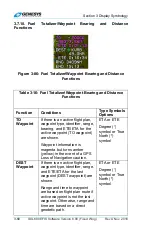
Table 3-16: Fuel Totalizer/Waypoint Bearing and Distance 

Functions 

Function 

Conditions 

Type Symbols 
Options 

DEST waypoint information is 
white but turns amber (yellow) 
in the event of a GPS Loss of 
Navigation caution. 

Range 

Aircraft range based upon 
instantaneous fuel flow, fuel 
remaining and groundspeed 
are shown immediately below 
DEST waypoint information for 
easy comparison.  


Endurance 

Aircraft endurance based upon 
instantaneous fuel flow and fuel 
remaining is shown.  


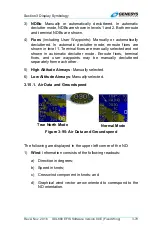
3.7.11.  Clock/Options 

The following are displayed in the upper right corner of the ND. 


Zulu Time


Local Offset Time


Figure 3-87: Clock Options 

Table 3-17: Clock/Options 

Feature 

Options 

Notes 

Zulu 
Time or 
Local 
Offset


Zulu or Local 

Shown in 

hh:mm:ss

 and 

synchronized with the GPS/SBAS 
constellation. 

Summary of Contents for IDU-680

Page 1: ......

Page 2: ...Rev A Nov 2016 IDU 680 EFIS Software Version 8 0E Fixed Wing i Pilot Operating Guide and Reference Document 64 000099 080E Fixed Wing EFIS Software Version 8 0E...

Page 3: ...d in any form or by any means without prior written consent of Genesys Aerosystems FlightLogic and Virtual VFR are trademarks of Genesys Aerosystems All other brand names and trademarks are the proper...

Page 4: ...EFIS Software Version 8 0E Fixed Wing iii Record of Revisions Retain this record in front of manual Upon receipt of a revision insert changes and complete table below Revision Number Revision Date In...

Page 5: ...nd Acronyms 2 4 2 2 System Overview 2 18 2 2 1 Functional Integration and Display Redundancy2 19 2 2 2 IDU Initialization 2 20 2 3 Software Safety Functions 2 24 2 3 1 Normal and Essential States 2 24...

Page 6: ...s 3 12 3 3 IDU 680 MFD Display Normal Mode 3 14 3 3 1 IDU 680 MFD Display Essential Mode Tapes 3 15 3 3 2 IDU 680 MFD in Normal Mode 3 16 3 4 Menu Functions 3 16 3 4 1 Selecting BARO 3 17 3 4 2 Select...

Page 7: ...e Indicator Round Dials 3 40 3 5 17 Landing Gear Indication Tapes and Round Dials 3 40 3 5 18 Unusual Attitude Mode Tapes 3 41 3 5 19 PFD Background Tapes only 3 42 3 5 20 Flight Path Marker Velocity...

Page 8: ...3 62 3 7 MFD Symbology 3 62 3 7 1 Ownship Symbology 3 63 3 7 2 Basic Moving Map 3 63 3 7 3 Moving Map with Instrument Approach 3 64 3 7 4 North Up Arc Mode 3 64 3 7 5 North Up Centered Mode 3 65 3 7...

Page 9: ...Active Flight Plan Path Manual Course Runways 3 75 3 13 FOV Indication 3 76 3 14 Range 3 76 3 15 Navigation Data 3 77 3 15 1 Air Data and Groundspeed 3 79 3 15 2 Analog Navigation Symbology 3 80 3 15...

Page 10: ...e 1 Normal Mode Tapes 4 17 4 3 1 PFD Failure Mode 1 Essential Mode Tapes 4 18 4 3 2 PFD Failure Mode 1 Essential Mode Round Dials 4 19 4 3 3 MFD Failure Mode 1 Normal Mode 4 20 4 4 PFD Failure Mode 2...

Page 11: ...de 6 Normal Mode 4 38 4 8 3 MFD Failure Mode 6 Essential Mode Tapes 4 39 4 9 PFD Failure Mode 7 Normal Mode Tapes 4 40 4 9 1 PFD Failure Mode 7 Normal Mode Round Dials 4 41 4 9 2 MFD Failure Mode 7 No...

Page 12: ...Level in Essential Mode 5 25 5 6 4 EICAS Page First Level Option Descriptions 5 27 5 7 EICAS Exceedance Menu 5 27 5 8 Expand CAS Menu 5 27 5 8 1 Expand CAS Menu Step By Step 5 28 5 9 Lower Level Menu...

Page 13: ...RAIM Prediction Step By Step 5 40 5 11 Active Flight Plan ACTV Menu 5 42 5 11 1 Active Flight Plan ACTV Menu Options 5 43 5 11 2 Active Flight Plan ACTV Menu Options Step By Step 5 47 5 11 3 Active Fl...

Page 14: ...Declutter DCLTR Menu Step By Step 5 72 5 21 PFD Altimeter Menu 5 72 5 21 1 PFD Altimeter Menu Step By Step 5 74 5 22 MFD Fault Display FAULTS Menu 5 75 5 22 1 PFD or MFD Fault Display FAULTS Menu Step...

Page 15: ...ading Source 7 21 7 4 2 GPS Altitude 7 22 7 4 3 Dead Reckoning 7 22 7 4 4 Geodesic Path Computation Accuracy 7 22 7 4 5 Parallel Offsets 7 22 7 5 Default GPS SBAS Navigation Modes 7 25 7 6 GPS SBAS CD...

Page 16: ...Functions 8 4 8 2 Terrain Display 8 5 8 3 Forward Looking Terrain Alert Function 8 6 8 3 1 FLTA Modes 8 7 8 3 2 GPS SBAS Navigation Mode Slaving 8 7 8 3 3 Default FLTA Mode 8 7 8 4 FLTA Search Envelop...

Page 17: ...g Tips 9 4 9 3 Domestic or International Flight Planning 9 4 9 3 1 Descent Planning 9 4 9 3 2 Terrain Clearance 9 4 9 3 3 Departure Airport Information 9 5 9 3 4 Unique Names for Flight Plans 9 5 9 3...

Page 18: ...5 Certification Basis 9 21 9 16 Environmental Requirements 9 22 T 1 Traffic Thumbnail Tapes only T 3 T 2 Traffic Display Definitions T 3 T 2 1 Traffic Rendering Rules T 3 T 3 Dedicated Traffic Screen...

Page 19: ...Step S 8 S 3 MFD Page PAGE Menu S 8 S 4 MFD Fault Display FAULTS Menu S 8 AR 1 Introduction AR 5 AR 2 Audio Radio Page AR 5 AR 2 1 Audio Radio System Colors AR 5 AR 2 2 Common Symbols AR 6 AR 2 3 VHF...

Page 20: ...enu Option Descriptions AR 32 AR 8 First Level Menu Option Descriptions AR 32 AR 9 1 Encoder AR 33 D 1 Datalink Symbology D 4 D 1 1 Ownship Symbol D 9 D 1 2 Datalink Screen Legend D 9 D 1 3 Air Data a...

Page 21: ...Manual Course Runways WX 6 WX 1 5 Weather Radar Return Data WX 7 WX 1 6 Air Data and Groundspeed WX 8 WX 1 7 Clock Timers Options WX 8 WX 1 8 Fuel Totalizer Waypoint Bearing and Distance Functions WX...

Page 22: ...Section 1 Introduction Rev A Nov 2016 IDU 680 EFIS Software Version 8 0E Fixed Wing 1 1 Section 1 Introduction...

Page 23: ...6 5 Replaced last image on page 6 10 6 Fixed wording in step 14 on page 7 40 7 Fixed wording in step 8 on page 7 53 8 Adjusted image in Figure 8 2 on page 8 6 9 Section 9 1 edited by deleting failure...

Page 24: ...NSTRATOR TRAINING APPLICATION 1 7 1 4 EFIS TRAINING TOOL 1 8 1 5 ABOUT THIS GUIDE 1 9 1 5 1 Audio and Video Interactive Capabilities 1 12 List of Figures FIGURE 1 1 IDU 680 INPUT IDENTIFICATION 1 5 FI...

Page 25: ...euvers Contrary to the traditional idea of overloading the pilot with information and options this Genesys Aerosystems EFIS clearly and concisely presents only necessary information This reduces pilot...

Page 26: ...gnated encoder and References in Section 5 Menu Functions and Step By Step Procedures refer to which encoder to push and or scroll for desired outcomes Between the two center encoders on the bezel a U...

Page 27: ...htness Panel lighting refers to the illumination of legends encoders and buttons push and scroll clockwise to increase and counter clockwise to decrease Display lighting refers to the illumination of...

Page 28: ...to fly anywhere in the world while performing any procedure except takeoff and landing based on the current Jeppesen navigation database To use this feature on the ground with the Ground Mode being e...

Page 29: ...e positioned anywhere in the world due to the worldwide terrain database loaded in the system by activating a flight plan stored in the memory However the Jeppesen navigation database must be updated...

Page 30: ...or MFD stored and activated in the same manner as on the EFIS displays installed in the aircraft This allows for moving the start point to anywhere in the world where loaded NavData is present for pra...

Page 31: ...ES Section 4 This section provides views of the IDU 680 displays with various sensor failed conditions and resulting symbology as well as examples of various configurations and display formats used wi...

Page 32: ...AWS all classes functionality for this fixed wing aircraft with all configurations Use this section for understanding the TAWS functions provided for the various phases of flight in addition to the ca...

Page 33: ...guide on a computer or mobile device click on the icons to hear the respective audio clip or watch a demonstration video via Genesys Aerosystems YouTube channel Check the YouTube channel for addition...

Page 34: ...Section 2 System Overview Rev A Nov 2016 IDU 680 EFIS Software Version 8 0E Fixed Wing 2 1 Section 2 System Overview...

Page 35: ...nu Philosophy 2 26 2 3 3 Avoidance of Autonomous Behavior 2 27 2 3 4 Data Source Monitors 2 27 2 3 5 IDU Intra System Communications 2 28 2 4 GENERAL ARRANGEMENT 2 28 2 5 EICAS DISPLAY 2 30 2 6 COLOR...

Page 36: ...ODE 2 25 FIGURE 2 4 MFD WITH EICAS ESSENTIAL MODE 2 26 FIGURE 2 5 PRIMARY IDU 680 PFI ON TOP HALF AND ND ON BOTTOM HALF 2 29 FIGURE 2 6 EICAS 2 30 FIGURE 2 7 PFD WITH EICAS 2 31 FIGURE 2 8 MFD WITH HS...

Page 37: ...c Flight Control System AFM Aircraft Flight Manual AGL Above Ground Level AHRS Attitude Heading Reference System AIRAC Aeronautical Information Regulation and Control AIRMET Airmen s Meteorological In...

Page 38: ...e to Altitude ARINC 424 Leg CALC as in RAIM R6 CAS Crew Alerting System CD Course to DME Distance ARINC 424 Leg CCW Counter Clockwise CDA Continuous Descent Approach CDI Course Deviation Indicator CDR...

Page 39: ...Representative dBZ Decibel relative to radar reflectivity Z DCLTR Declutter DCN Document Change Notice DCND Descend DEC HT Decision Height Bug DEL Delete DEM Digital Elevation Model DER Designated Eng...

Page 40: ...ahrenheit FA Course from a Fix to Altitude ARINC 424 Leg FAA Federal Aviation Administration FAF Final Approach Fix FAR Federal Aviation Regulation FAWP Final Approach Waypoint same as FAF FC Course F...

Page 41: ...Australia s Ground Based Augmentation System GLONASS Russian Global Navigation Satellite System GLS GNSS Landing System GMETAR Graphical METAR also GMTR GMF Ground Maintenance Function GN Gain GND Gr...

Page 42: ...h Procedure Initial Approach Point IAS Indicated Airspeed IAWP Initial Approach Waypoint same as IAP IC Integrated Circuit ICAO International Civil Aviation Organization ICD Interface Control Document...

Page 43: ...rystal Display LCL Local LDA Localizer type Directional Aid LED Light Emitting Diode LGND Legend LIFR Low IFR conditions Ceiling 100 or visibility 1 mile LNAV Lateral Navigation LOC Localizer LOI Loss...

Page 44: ...owing multiple display screens MIN Minimum MM Middle Marker MMO Maximum Operating Mach Number MOA Military Operations Area MOPS Minimum Operational Performance Standard MOT Mark On Target MSAS Japan s...

Page 45: ...T Next OASIS Open Architecture Systems Integration Symbology OAT Outside Air Temperature OBS Omnibearing Selector ODP Obstacle Departure Procedure OF Over fly OM Outer Marker OT Other Traffic Traffic...

Page 46: ...ter setting provides height above reference point QM Quality Management QNE Altimeter setting provides pressure altitude readout QNH Altimeter setting provides MSL altitude at a reporting point RA Res...

Page 47: ...SAT Saturation SBAS Satellite Based Augmentation System SCC System Configuration Card personality module SCI Software Configuration Index SCMP Software Configuration Management Plan SCR Software Conf...

Page 48: ...tability STAR Standard Terminal Arrival Routes STBY Stand by STC Supplemental Type Certificate STP Software Test Protocol STRKS Strikes Lightning detection STS Software Test Specification SUA Special...

Page 49: ...fic Information Service TIS B Traffic information Service Broadcast TLT Tilt TMS Texas Instruments family of DSP processors TQP Tool Qualification Plan TRANS Transition TRK Track TRNDO Tornadic TSO Te...

Page 50: ...ERT Vertical VFE Maximum flap extended speed VFOM Vertical Figure of Merit VFR Visual Flight Rules VGL Best glide speed in speed units at gross weight with gear and flaps retracted VHF Very High Frequ...

Page 51: ...ngle of climb WAAS Wide Area Augmentation System WGS84 World Geodetic System 1984 WPT Waypoint WX Weather XFILL Cross fill 2 2 System Overview The IDU 680 EFIS is a complete flight and navigation inst...

Page 52: ...nal display architectures where most of these functions were performed by external LRUs Figure 2 1 depicts a typical architecture used by IDUs The IDUs depend upon intra system between IDUs on a side...

Page 53: ...multi screen installation with a 1 IDU transmits this configuration to the other IDUs including all Co Pilot System IDUs Upon reception of the configurations transmission from the Pilot System 0 or 1...

Page 54: ...e set to off 15 PFD zoom mode is set to off 16 Manual RNP is set to off 17 PFD skyway is set to on 18 V speeds are cleared 19 RDR 2000 2100 scale is initialized to 80NM 20 Crosslink is initialized to...

Page 55: ...n elevation at the startup point Providing the Baro Autosetting on Startup is enabled 6 A logo screen displaying a Software CRC 32 b Aircraft Type c OASIS configuration name and CRC 32 d Audio Radio c...

Page 56: ...file created during the last ground boot is checked If the bit result file indicates a failure the program exits with an error message If the bit result file indicates passage the program continues 3...

Page 57: ...e top area and a pilot selectable multi function page in the bottom area 2 3 1 Normal and Essential States Figure 2 2 Normal Mode Normal state for IDUs configured as 2 is a pilot selectable EICAS page...

Page 58: ...rea and EICAS in the bottom area and is always available with a single button press R5 The state is designed to provide the pilot with everything needed for continued safe operation on a single screen...

Page 59: ...e following rules are in the design of the menu system EXIT R1 Whenever the menu system is beyond the top level EXIT R1 provides a one touch escape to the top level BACK L1 Whenever a soft menu level...

Page 60: ...cedence of the IDUs based upon the IDU number IDU 1 always shows the essential flight instruments because the PFI page is always shown in the top area Lower priority IDUs monitor the higher priority I...

Page 61: ...d agreement 8 Heading agreement 9 Localizer and glideslope deviation agreement 10 Radar altitude agreement 2 4 General Arrangement The IDU 680 is 7 500 W x 10 250 H x 4 750 D and weighs less than 9 5...

Page 62: ...IDU is independent from all other IDUs In an IFR installation the software of the primary IDU 680 is configured so only the primary screen Primary Flight Information PFI display top half plus Multi Fu...

Page 63: ...display may be shown at any time The only limitation to this rule is since IDU 680s are configured as a primary display of engine information at least one of the Multi Function Display areas must sho...

Page 64: ...Section 2 System Overview Rev A Nov 2016 IDU 680 EFIS Software Version 8 0E Fixed Wing 2 31 Figure 2 7 PFD with EICAS...

Page 65: ...presentation may not be identical as it appears on the IDU WHITE is used for items set by the pilot and held internally by the EFIS system or items where device feedback is not expected such as STBY f...

Page 66: ...enabled indications and IDENT indication Used to indicate electronically calculated or derived data and certain navigation database items Examples Active waypoint related symbols Course data desired t...

Page 67: ...moving map and advisory text on black background RED is used to indicate aircraft limitations or conditions which require immediate pilot action Currently only used to indicate a device failure red X...

Page 68: ...Fuel Low Fuel Low One of the following condi tions is true 1 One of the low fuel warning discrete inputs is active 2 One of the sensed fuel tank quantities is below its low fuel warning threshold 3 T...

Page 69: ...higher of VS1 or VS1 corrected for G load 5 KIAS Deactivated if stall warning flag set to 0 No time delay Traffic Traffic Resolution advisory Not given if own aircraft below 400 AGL Not given if targe...

Page 70: ...ndicates no valid bank pitch or heading received from AHRS 1 for more than 1 second No delay Inhibited during and for 10 seconds after unusual attitude mode Alert Tone Only active in dual AHRS install...

Page 71: ...n AHRS is beyond limits 6 10 second time delay Inhibit for 5 minutes after startup Auxiliary Sensor Failure Auxiliary Sensor Failure No valid message or bad status received from installed optional sen...

Page 72: ...system monitor message has been received from the trans mitting display checks intra system monitor mes sages Indicates either 1 the screen counter value has not changed in the last 1 second 0 1 secon...

Page 73: ...last waypoint if it is active or 2 airport if on a missed approach or 3 along route distance to destination Not activated in climbing flight nor if below 60 knots groundspeed 5 minute time delay Fuel...

Page 74: ...on threshold Only performed if the Fuel Split caution threshold is non zero and both left and right wing tank fuel are monitored and valid 1 minute time delay Glideslope Glideslope Within GPWS Mode 5...

Page 75: ...condition Indicates position track or groundspeed difference between GPS SBAS units is beyond limits Limits are as follows Position Enroute Mode 4NM Terminal Mode 2NM Departure Mode 6NM IFR Approach M...

Page 76: ...ore than 5 seconds No time delay Inhibited during and for 10 seconds after unusual attitude mode Alert Tone Only active in dual GPS SBAS installation Indicates no valid message received from GPS SBAS...

Page 77: ...nals is beyond limits 0 25 Dots 10 second time delay Alert Tone Only active in dual AHRS installation with neither AHRS in failure condition nor in DG mode Indicates heading difference between AHRS is...

Page 78: ...signals is beyond limits 0 25 Dots 10 second time delay Alert Tone No valid heading received from selected AHRS for more than 1 second Inhibited during and for 10 seconds after unusual attitude mode D...

Page 79: ...ata parameters are normal i e air data is not red X d Half second time delay Caution Obstruction Caution Obstruction Obstruction within TAWS FLTA caution envelope Half second time delay Alert Tone Onl...

Page 80: ...ompare logic 5 Localizer both inputs use Localizer Miscompare logic 6 Glideslope both inputs use Glideslope Mis compare logic 7 Radar Altitude use Radar Altitude Miscompare logic 8 Latitude Use GPS SB...

Page 81: ...second time delay Alert Tone Indicates SCC card Personality Module could not be read upon power up Limits internal to the IDU are in use by the system Only active on the ground Alert Tone Only active...

Page 82: ...ore than 1 second Also displayed in Ground Mode Inhibited when radar altimeter value received from ARINC 429 except when SSM of radar altimeter message indicates failure warning 2 second time delay Al...

Page 83: ...ence between radar altimeters is beyond limits Limits are 500 AGL 14 100 500 AGL 10 100 AGL 10 10 second time delay Alert Tone Indicates either 1 the ADC is not transmitting SSEC corrected data on an...

Page 84: ...both systems are oper ating from same ADC source No time delay Alert Tone Only active in dual system pilot and co pilot dual AHRS installation with good inter system communications and nei ther AHRS...

Page 85: ...No time delay Alert Tone Only active in dual system pilot and co pilot with good inter system com munications Indicates both systems are operating from same navigation source Alert inhibited if both s...

Page 86: ...TCAS II TCAS I or TAS system Indicates lack of communications with system or failure indication from system No time delay Caution Terrain Caution Terrain Terrain cell within TAWS FLTA caution envelope...

Page 87: ...ed if 1 totalizer mismatch caution threshold is non zero 2 fuel totalizer is enabled 3 unmonitored fuel flag is false 4 fuel totalizer has a valid value and 5 fuel levels are valid 1 minute time delay...

Page 88: ...rimmed for more than 3 continuous seconds i e trim is not responding UP trim is needed Alert Tone Only active in dual system pilot and co pilot Indi cates lack of inter system communications 2 second...

Page 89: ...w minimum altitude bug Causes minimum altitude readout to turn amber yellow and flash No time delay ADVISORIES Chime Only active in dual AHRS installation Indicates AHRS 1 in DG mode No time delay Chi...

Page 90: ...in 10 seconds Disabled during QFE oper ation 2 second time delay Chime Only with EFIS control of an audio controller with pilot isolate function and call notice is received from the controller Chime G...

Page 91: ...LNAV VNAV Approach Mode No time delay Chime GPS SBAS in LP Approach Mode No time delay Chime GPS SBAS in LPV Approach Mode No time delay None Number of active messages exceeds 11 Guides pilot in acce...

Page 92: ...manual GPS SBAS OBS or being in holding prior to activating the CONTINUE tile No time delay Chime Only active with TCAS II system Indicates TCAS II system is unable to display resolution adviso ries N...

Page 93: ...nd system is operating in True North Mode No time delay Chime GPS SBAS in Vectors to Final Approach Mode prior to sequencing FAWP No time delay Chime GPS SBAS in VFR Approach Mode No time delay Chime...

Page 94: ...nly active with Intelliflight 1950 Aural message given when autopilot servos disengage for any reason Autopilot Failure Only active with Intelliflight 1950 Aural message given when an autopilot failur...

Page 95: ...nowledged by pressing the audio mute switch Caution flags flash at 1 Hz until acknowledged by pressing the audio mute switch Only the highest priority in criticality and recency unacknowledged aural a...

Page 96: ...y Microsoft Excel or similar spreadsheet software In addition data from the previous four flights is kept in files caslog01 csv through caslog04 csv Upon system start the existing caslog00 csv through...

Page 97: ...ezel upward to the first detent position to expose the USB port Figure 2 9 Ground Maintenance Page 2 8 2 Update Requirements When an update is performed the procedures must be performed on every IDU i...

Page 98: ...use erroneous failure indications or corruption of the IDU The obstruction database is distributed by a government agency in each country but not all countries have obstruction databases available Onc...

Page 99: ...erations are intended 1 Airports 2 VORs DMEs including DMEs collocated with localizers collocated VOR DMEs VORTACs and NDBs including NDBs used as locator outer marker 3 All named waypoints and inters...

Page 100: ...sults in loading the appropriate waypoints and legs into the flight plan Waypoints utilized as a final approach waypoint FAWP or missed approach waypoint MAWP in an LNAV approach procedure are uniquel...

Page 101: ...ome familiar with the many features of the Genesys Aerosystems EFIS 2 9 1 Application Software Air Mode and Ground Mode Numerous symbology elements change behavior depending upon whether the aircraft...

Page 102: ...Section 3 Display Symbology Rev A Nov 2016 IDU 680 EFIS Software Version 8 0E Fixed Wing 3 1 Section 3 Display Symbology...

Page 103: ...s 3 15 3 3 2 IDU 680 MFD in Normal Mode 3 16 3 4 MENU FUNCTIONS 3 16 3 4 1 Selecting BARO 3 17 3 4 2 Selected Altitude Sub Mode Target Altitude Tapes 3 19 3 4 3 VNAV Sub Mode 3 20 3 4 4 Altitude Displ...

Page 104: ...tion Tapes and Round Dials 3 40 3 5 18 Unusual Attitude Mode Tapes 3 41 3 5 19 PFD Background Tapes only 3 42 3 5 20 Flight Path Marker Velocity Vector Basic Mode Tapes 3 46 3 5 21 Bank Angle Scale Ta...

Page 105: ...7 1 Ownship Symbology 3 63 3 7 2 Basic Moving Map 3 63 3 7 3 Moving Map with Instrument Approach 3 64 3 7 4 North Up Arc Mode 3 64 3 7 5 North Up Centered Mode 3 65 3 7 6 Heading Up Centered Mode 3 6...

Page 106: ...AL COURSE RUNWAYS 3 75 3 13 FOV INDICATION 3 76 3 14 RANGE 3 76 3 15 NAVIGATION DATA 3 77 3 15 1 Air Data and Groundspeed 3 79 3 15 2 Analog Navigation Symbology 3 80 3 15 3 Borders 3 81 3 15 4 Terrai...

Page 107: ...LLY INTEGRATED TAPES 3 20 FIGURE 3 16 VNAV SUB MODE VERTICALLY INTEGRATED TAPES 3 20 FIGURE 3 17 ALTITUDE DISPLAY VNAV TILE 3 21 FIGURE 3 18 ALTITUDE DISPLAY METRIC UNITS 3 21 FIGURE 3 19 PFD SYMBOLOG...

Page 108: ...FORCE INDICATOR TAPES 3 39 FIGURE 3 48 G FORCE INDICATOR TELLTALE INDICATIONS TAPES 3 39 FIGURE 3 49 RESET G 3 39 FIGURE 3 50 FAST SLOW INDICATOR TAPES 3 40 FIGURE 3 51 G FORCE INDICATOR ROUND DIALS 3...

Page 109: ...IP SYMBOLOGY 3 63 FIGURE 3 78 OWNSHIP SYMBOLS 3 63 FIGURE 3 79 BASIC MOVING MAP 3 63 FIGURE 3 80 MOVING MAP WITH INSTRUMENT APPROACH 3 64 FIGURE 3 81 NORTH UP ARC MODE 3 64 FIGURE 3 82 NORTH UP CENTER...

Page 110: ...RE 3 100 PAN MODE 3 85 FIGURE 3 101 HSI OWNSHIP SYMBOL 3 86 FIGURE 3 102 HSI POINTER COLOR 3 86 FIGURE 3 103 ANALOG NAVIGATION DISPLAY VOR1 AND VOR2 3 87 FIGURE 3 104 HSI BEARING DISTANCE READOUT WITH...

Page 111: ...all other IDU 680 displays so any screen display may be shown at any time The only limitation is where IDU 680 displays are configured as a primary display of engine information at least one of the M...

Page 112: ...Section 3 Display Symbology Rev A Nov 2016 IDU 680 EFIS Software Version 8 0E Fixed Wing 3 11 3 2 1 IDU 680 PFD Display Normal Mode with EICAS Tapes Figure 3 2 PFD in Normal Mode with EICAS Tapes...

Page 113: ...a traditional attitude display with the airspeed altitude and heading scales appearing in blacked out areas in a Basic T arrangement but is disabled while Unusual Attitude Mode is active The following...

Page 114: ...t Compass Rose Detected on ND When round dial instruments are enabled the following are no longer present when Basic Mode is displayed 1 Atmospheric perspective 2 Airspeed trend 3 Terrain rendering 4...

Page 115: ...ection 3 Display Symbology 3 14 IDU 680 EFIS Software Version 8 0E Fixed Wing Rev A Nov 2016 3 3 IDU 680 MFD Display Normal Mode Figure 3 5 MFD in Normal Mode with MAP Page Displayed on Top and Bottom...

Page 116: ...Section 3 Display Symbology Rev A Nov 2016 IDU 680 EFIS Software Version 8 0E Fixed Wing 3 15 3 3 1 IDU 680 MFD Display Essential Mode Tapes Figure 3 6 MFD in Essential Mode with EICAS Tapes...

Page 117: ...4 Menu Functions Soft menu functions are used at both levels and displayed in the screen margins Soft menu function tiles include an indication of further menu levels with a filled triangle with furth...

Page 118: ...oo long to be presented in the space available provide an indication of location within the list Whenever the menu system is beyond the top level EXIT R1 provides a one touch escape to the top level W...

Page 119: ...e mode is identified as QFE operations otherwise no mode is indicated QFE Barometric setting resulting in the altimeter displaying height above a reference elevation i e airport or runway threshold QN...

Page 120: ...t altitude bug setting annunciation is green while the target altitude bug is filled white when in altitude hold mode When in a climb or descent mode the target altitude bug setting annunciation is wh...

Page 121: ...tegrated with an autopilot either fully or partially integrated through use of the vertical mode discrete input as a control parameter for climbs or descents Figure 3 15 VNAV Sub Mode Not Vertically I...

Page 122: ...y Metric Units Tapes Pilot selectable altitude values may be presented in metric units with a resolution of ten meters Figure 3 18 Altitude Display Metric Units 3 5 PFD Symbology Tapes The PFD combine...

Page 123: ...isplayed in the appropriate position on the altitude tape and below in amber yellow The minimum altitude setting is indicated with a line drawn below In Figure 3 20 760 MSL is set The minimum and targ...

Page 124: ...arest ten feet as adjusted by an altimeter setting The altitude dial shows a 1000 foot range with labels and graduations every 100 feet Clockwise rotation of the pointer and corresponds to increasing...

Page 125: ...white at all times When in VNAV sub mode the altitude dial shows the active waypoint VNAV altitude if it exists with a triangular VNAV altitude bug with a resolution of 100 feet The VNAV altitude bug...

Page 126: ...with green and red regions to provide RA maneuver guidance Without TCAS II 3 000 FPM 500 1 000 2 000 and 3 000 FPM The VSI worm grows in proportion to the square root of the vertical speed so a change...

Page 127: ...SI limits as described for the tapes vertical speed indicator Table 3 1 The readout digitally displays vertical speed rounded to the nearest 100 feet per minute Clockwise upward rotation of the pointe...

Page 128: ...ay of the currently set decision height Decision height turns amber yellow and flashes when the aircraft descends below decision height This is accompanied by Decision Height aural annunciation and ca...

Page 129: ...mbnail Likewise when the Analog AGL altitude display is shown the normal AGL display is removed Table 3 4 Analog AGL Indicator Markings Major Tick Marks Minor Tick Marks 0 10 20 30 40 50 60 70 80 90 1...

Page 130: ...r yellow and flashes 3 5 8 Decision Height Round Dials Decision height turns amber yellow and flashes when aircraft descends below decision height Figure 3 30 Decision Height Round Dials 3 5 9 Airspee...

Page 131: ...e the bug appears to be parked as in this example Figure 3 32 Airspeed Trend Tapes Table 3 5 Airspeed Bug Limits Low end High end Higher of 1 2 x Vs or 60KIAS Red line VNE VMO or MMO Table 3 6 Airspee...

Page 132: ...rom VS1 to VNO The airspeed readout is green in this area b An amber yellow caution area from VNO to VNE The airspeed readout is amber yellow in this area c A red high speed awareness area from VNE to...

Page 133: ...area and green in the normal operating area d If a valid VFE does not exist a gray normal operating area from G compensated 1 2 x VS0 to the lower of VMO or MMO The airspeed readout is green in this...

Page 134: ...er VS0 is calculated by dividing the pilot input VREF by 1 23 2 If enabled VGL not 0 a green dot best glide speed marker at VGL 3 If enabled VX not 0 a VX marking at VX 4 If enabled VY not 0 a VY mark...

Page 135: ...ls a black circle with red X is shown instead of the airspeed readout dial and pointer Figure 3 36 ADC Sensor Failed Round Dials Airspeed markings are as described for the tapes airspeed indicator The...

Page 136: ...rth with graduations every 5 with major graduations and heading labels every 10 These graduations and digits of the heading scale are equally spaced so at an aircraft roll angle of zero they approxima...

Page 137: ...le has a pilot settable heading bug symbol designed to geometrically interact with the heading pointer When the heading bug is set the value is displayed in a white bordered black box above the headin...

Page 138: ...al mode the heading display appears in a blacked out area on the bottom to emulate a Basic T The heading display automatically declutters when a compass rose is detected in the bottom area When AHRS i...

Page 139: ...er to present the fewest possible increments needed to unambiguously display pitch attitude The pitch scale terminates with a zenith symbol small white circle at 90 and a nadir symbol small white circ...

Page 140: ...rd as indicated airspeed further decreases 3 5 15 G Force and Fast Slow Indicator Tapes G Force indicator appears in the Normal Mode as depicted or next to the Large Aircraft Symbol Reference Marks Ba...

Page 141: ...higher than the target and is decluttered when on the ground 3 5 16 G Force Indicator Round Dials A G Force indicator display with a readout dial pointer and scale sufficient to accommodate any G For...

Page 142: ...ive and negative appear to aid in unusual attitude recovery NOTE Recovery chevrons are a normal part of the pitch scale and are not necessarily tied to unusual attitude mode The following features are...

Page 143: ...as two pilot selectable field of view FOV modes wide FOV mode approximately 70 and narrow FOV mode approximately 35 In Unusual Attitude Mode wide FOV mode is automatically selected The terrain and obs...

Page 144: ...s to create a realistic depiction of the horizon At latitudes greater than 75 no grid lines are shown To keep the grid spacing relatively consistent at latitudes between 45 and 75 the longitude spacin...

Page 145: ...d band to prevent grid flicker while flying along one of the boundary latitudes The grid space switching changes at one degree less latitude when flying towards the Equator than it does when flying to...

Page 146: ...ditionally terrain may be deselected on the PFD and retained on the ND MAP display as seen in Figure 3 55 WARNING MANY TOWERS ANTENNAS STRUCTURES AND OBSTRUCTIONS ARE NOT IN THE DATABASE Figure 3 55 P...

Page 147: ...are depicted on the PFD in SVS Basic or SVS TAWS modes 1 Narrow FOV 17NM 2 Wide FOV 12NM NOTE The obstruction data is provided by Jeppesen and must be updated each 28 days to maintain current databas...

Page 148: ...d from the display The flight path marker is not shown in Basic Mode In Unusual Attitude Mode it disappears to allow the pilot to concentrate on the Large Aircraft Symbol Reference Marks for unusual a...

Page 149: ...d sky pointer appear full time with level 10 20 30 45 and 60 marks on left and right sides 3 5 22 Turn Rate Indicator Tapes Rate of turn is available as an option in the PFD Declutter menu to show a w...

Page 150: ...3 61 Timer 3 5 25 Marker Beacon Symbology Tapes Marker beacons data acquired from the Navigation Receiver are displayed on the PFD and disabled when the selected NAV source is FMS Valid marker beacon...

Page 151: ...ght Director with one of the following symbols shown in Normal Mode The PFD has a waterline symbol fixed in the center of the display Rotation of the background pitch scale and background oriented dis...

Page 152: ...FD2 Basic Mode without Compass Rose Detected on ND Tapes 3 5 28 Course Deviation Indicator Tapes Figure 3 67 Course Deviation Indicator Tapes Table 3 11 CDI Behavior and Color CDI Pointer and Conditio...

Page 153: ...n entering enroute mode From Terminal to Approach If VTF switch immediately Otherwise change from 1 NM FSD to approach FSD over distance of 2 NM start transition at 2 NM from FAWP From Approach to Ter...

Page 154: ...ce VOR2 EFIS coupled system with autopilot Holding the wings level Tracking HDG BUG LNAV in ARM mode LNAV captured Notes No positive autopilot feedback Positive autopilot feedback 3 5 29 OBS Setting o...

Page 155: ...UG Heading Bug Sub Mode Guidance 4 HDG Failure Sub Mode 3 5 31 Vertical Deviation Indicator The PFD has a vertical deviation indicator on the right side to display vertical deviation for the currently...

Page 156: ...anticipation as long as the following are true 1 On VNAV descent segments or 2 If the vertical deviations on VNAV level segments option is enabled on VNAV level segments or 3 If the vertical deviatio...

Page 157: ...llow guidance to LPV minima regardless of temperature LPV2 When descending on final approach segment in LPV mode 2 LNAV Mode and VNAV1 G or VNAV2 G When descending on the final approach segment in LP...

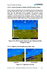
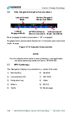
Page 158: ...put with the glideslope mode engaged the selected vertical navigation source is green to indicate the autopilot is vertically coupled to the selected vertical navigation source Otherwise the selected...

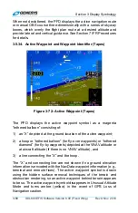
Page 159: ...1 an X depicted at the ground location of the active waypoint 2 a hoop or tethered balloon for fly over waypoints or tethered diamond for fly by waypoints depicted at the VNAV altitude or at aircraft...

Page 160: ...s the current active waypoint is passed With terrain turned off the active waypoint is always visible regardless of distance If the active waypoint is beyond the lateral limits of the screen the magen...

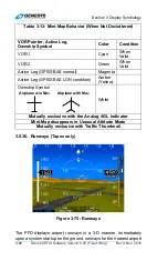
Page 161: ...ive Leg GPS SBAS normal Magenta Active Leg GPS SBAS LON condition Amber Yellow Ownship Symbol White Mutually exclusive with the Analog AGL Indicator Mini Map disappears in Unusual Attitude Mode Mutual...

Page 162: ...atabase including elevation position orientation length and width The landing portion of the selected runway taking into account displaced threshold data is shown in light gray When the depiction of a...

Page 163: ...3 76 Autopilot Annunciation NOTE For all autopilot annunciations and symbology see applicable autopilot operating handbook and or AFM AFMS 3 7 MFD Symbology The Navigation Display is presented in a va...

Page 164: ...tware Version 8 0E Fixed Wing 3 63 3 7 1 Ownship Symbology Figure 3 77 Ownship Symbology Figure 3 78 Ownship Symbols 3 7 2 Basic Moving Map Figure 3 79 Basic Moving Map Airplane FAR 23 with VNE Airpla...

Page 165: ...ymbology 3 64 IDU 680 EFIS Software Version 8 0E Fixed Wing Rev A Nov 2016 3 7 3 Moving Map with Instrument Approach Figure 3 80 Moving Map with Instrument Approach 3 7 4 North Up Arc Mode Figure 3 81...

Page 166: ...ng 3 65 3 7 5 North Up Centered Mode Figure 3 82 North Up Centered Mode 3 7 6 Heading Up Centered Mode Figure 3 83 Heading Up Centered Mode 3 7 7 Waypoint Symbology The ND displays navigation symbolog...

Page 167: ...ude Airway VOR User Waypoint 3 7 8 Conventional HSI PTR Format The ownship symbol Figure 3 78 is centered and pointing straight up on the HSI The HSI has a compass rose aligned with either magnetic No...

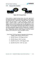
Page 168: ...s track across the earth appears on the compass rose but is not displayed when groundspeed is less than 30 knots The pilot settable heading bug geometrically interacting with the heading pointer appea...

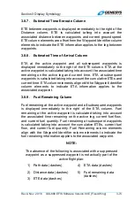
Page 169: ...ype identifier range bearing and ETE ETA for the active waypoint TO waypoint are shown Waypoint information is magenta but turns amber yellow in the event of a GPS Loss of Navigation caution ETA or ET...

Page 170: ...e based upon instantaneous fuel flow fuel remaining and groundspeed are shown immediately below DEST waypoint information for easy comparison Endurance Aircraft endurance based upon instantaneous fuel...

Page 171: ...led Terrain status is indicated by the absence or presence of terrain 3 8 Navigation Log Figure 3 88 Navigation Log 3 8 1 Clock and Groundspeed The following are displayed in the upper left corner of...

Page 172: ...ed Approach Point 3 MA Waypoint is part of the missed approach segment of an Instrument Approach Procedure 4 APP Waypoint is part of an Instrument Approach Procedure but not a Final Approach Fix Misse...

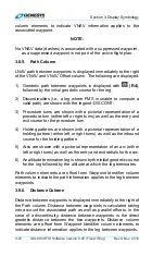
Page 173: ...tterns are shown with a pictorial representation of a holding pattern either left or right turns as well as the inbound course for the holding pattern 5 Arcs are shown with a pictorial representation...

Page 174: ...s and current time ETA column elements align with the Waypoint Identifier column elements to indicate ETA information applies to the associated waypoint 3 8 9 Fuel Remaining Column Fuel remaining at t...

Page 175: ...3 10 Altitude Capture Predictor Top of Descent Figure 3 90 Top of Descent or Top of Climb When a selected altitude or VNAV is specified on the PFD the point at which a descent must commence is marked...

Page 176: ...SBAS path definition and matches lateral navigation guidance given on the PFD GPS SBAS CDI in automatic OBS mode skyway boxes and mini map The symbol for fly over waypoints is distinct from fly by wa...

Page 177: ...tabase including position orientation length and width 3 13 FOV Indication The ND background indicates the ND FOV with a set of segmented gray lines leading out from the ownship symbol in either 35 or...

Page 178: ...gure 3 93 Range 3 15 Navigation Data Figure 3 94 Navigation Data and Airspace Depiction The ND displays navigation data in correct relationship to the ownship symbol with navigation data symbols inclu...

Page 179: ...Restricted Areas when equipped with Datalink Red The ND has manual and automatic decluttering of navigation data There are six levels of automatic declutter based upon the number of potential navigati...

Page 180: ...selected and not shown in automatic declutter mode Enroute fixes terminal fixes and user waypoints may be manually decluttered separately from each other 5 High Altitude Airways Manually selected 6 L...

Page 181: ...d OAT Decluttered if the Show ISA Temperature Flag is disabled in EFIS limits 4 Density Altitude Digitally in feet Decluttered if the Show Density altitude Flag is disabled in EFIS limits 5 True Airsp...

Page 182: ...sion 8 0E Fixed Wing 3 81 Figure 3 96 Analog Navigation Symbology 3 15 3 Borders National and United States state borders are drawn if selected at all map scales They are white if the ND background in...

Page 183: ...n the ND in correct relationship to the ownship symbol using color to show relationship to aircraft altitude Table 3 19 Terrain Display on Navigation Display Color Relationship to Aircraft Altitude Ba...

Page 184: ...ude Shades of Brown 1 FLTA alerts Amber and Red 2 Water at all altitudes Deep Blue 3 Note 1 Slope between adjacent terrain pixels in an increasing longitude direction determines shade Note 2 See Secti...

Page 185: ...NM or greater Not depicted on the ND 8 5 NM or less As described below Vertical Criteria More than 2000 below the aircraft Not depicted on the ND Within 2000 but more than 500 below aircraft Depicted...

Page 186: ...location and viewing map details along the route of flight and at the intended or alternate destination while in flight or on the ground When pan mode is active use labeled buttons to pan location no...

Page 187: ...ompass rose aligns with either magnetic North or True North depending on the status of True North input The ownship symbol points straight up and when the HSI NAV source fails FMS VOR1 or VOR2 a red X...

Page 188: ...isplayed on the PFD with the exception of the VDI source displayed on the top of the VDI to avoid clutter with waypoint information below See 3 5 31 for clarification of the conformance to VDI display...

Page 189: ...ME channel is in hold mode the DME s channel hold frequency is also amber yellow Figure 3 105 When the hold function for the associated DME channel is enabled HOLD L5 sets the hold frequency of the DM...

Page 190: ...dout with DME in HOLD Figure 3 106 HSI with Marker Beacon Displayed Tapes Valid Marker Beacon discretes are displayed as indicators on the PFD and ND HSI display Figure 3 106 with appropriate coloring...

Page 191: ...ociated with HSI source shown When HSI source is FMS FMS OBS setting matches OBS setting shown on the PFD FMS CDI FMS OBS setting is labeled A automatic or M manual When HSI is slaved to GPS SBAS and...

Page 192: ...Section 4 Reversionary Modes Rev A Nov 2016 IDU 680 EFIS Software Version 8 0E Fixed Wing 4 1 Section 4 Reversionary Modes...

Page 193: ...nd Dials 4 15 4 2 2 MFD Failure Mode 0 Normal Mode 4 16 4 3 PFD FAILURE MODE 1 NORMAL MODE TAPES 4 17 4 3 1 PFD Failure Mode 1 Essential Mode Tapes 4 18 4 3 2 PFD Failure Mode 1 Essential Mode Round D...

Page 194: ...MODE TAPES 4 36 4 8 1 PFD Failure Mode 6 Normal Mode Round Dials 4 37 4 8 2 MFD Failure Mode 6 Normal Mode 4 38 4 8 3 MFD Failure Mode 6 Essential Mode Tapes 4 39 4 9 PFD FAILURE MODE 7 NORMAL MODE TA...

Page 195: ...NORMAL TAPES 4 24 FIGURE 4 13 PFD FAILURE MODE 3 NORMAL MODE AHRS FAILED GPS SBAS AND ADC NORMAL TAPES 4 25 FIGURE 4 14 PFD FAILURE MODE 3 NORMAL MODE AHRS FAILED GPS SBAS AND ADC NORMAL ROUND DIALS 4...

Page 196: ...D GPS SBAS NORMAL 4 38 FIGURE 4 27 MFD FAILURE MODE 6 ESSENTIAL MODE ADC AND AHRS FAILED GPS SBAS NORMAL TAPES 4 39 FIGURE 4 28 PFD FAILURE MODE 7 NORMAL MODE GPS SBAS ADC AND AHRS FAILED TAPES 4 40 F...

Page 197: ...SBAS normal Mode 7 GPS ADC and AHRS failed To use this section review the following table and notes to determine what feature or function is affected by one or more of the three sensors failed condit...

Page 198: ...ading Scale 7 7 7 7 7 7 AGL Ind OK 2 4 OK 11 11 4 Flight Path Marker OK 1 14 G meter OK OK OK OK Ground Track 7 1 7 7 7 Heading Indicator 7 7 7 7 Horizon OK OK OK OK Mini Map 7 1 7 7 7 Pitch Limit Ind...

Page 199: ...nctions OK OK OK OK OK OK OK OK Waypoint Brg Dist OK 1 OK OK OK Wind 21 3 WX 500 Data OK OK OK OK OK OK OK OK Compass Rose 9 9 9 9 9 9 Fuel Totalizer Functions 23 24 23 23 12 12 12 12 True Airspeed OK...

Page 200: ...and heading indication is removed In heading only failure mode or AHRS failure mode combined with GPS failure heading scale is replaced with a red X Note 8 Based upon 1G stall speed Note 9 In heading...

Page 201: ...tion is presented Note 25 Inhibited in accordance with the conditions specified in TAWS Automatic Inhibit Function Abnormal Operation 4 1 1 Oat Sensor Failure Mode In addition the equipment has an OAT...

Page 202: ...O ESSNTL R5 to alternate between Normal and Essential Modes on all displays Essential Mode consists of a PFD screen in the top area and if configured an Essential Mode EICAS screen in the bottom area...

Page 203: ...etects a position failure that cannot be excluded within time to alert when integrity is provided by FDE e HPL HAL on the final approach segment Genesys Aerosystems EFIS does not transition to DR Navi...

Page 204: ...ment malfunction or failure c The presence of a condition where fault detection detects a position failure that cannot be excluded d There are an insufficient number of SBAS HEALTY satellites e The ho...

Page 205: ...ion 4 Reversionary Modes 4 14 IDU 680 EFIS Software Version 8 0E Fixed Wing Rev A Nov 2016 4 2 PFD Failure Mode 0 Normal Mode Tapes Figure 4 2 PFD Failure Mode 0 Normal Mode GPS ADC and AHRS Normal Ta...

Page 206: ...eversionary Modes Rev A Nov 2016 IDU 680 EFIS Software Version 8 0E Fixed Wing 4 15 4 2 1 PFD Failure Mode 0 Normal Mode Round Dials Figure 4 3 PFD Failure Mode 0 Normal Mode GPS ADC and AHRS Normal R...

Page 207: ...Section 4 Reversionary Modes 4 16 IDU 680 EFIS Software Version 8 0E Fixed Wing Rev A Nov 2016 4 2 2 MFD Failure Mode 0 Normal Mode Figure 4 4 MFD Failure Mode 0 Normal Mode GPS ADC and AHRS Normal...

Page 208: ...Modes Rev A Nov 2016 IDU 680 EFIS Software Version 8 0E Fixed Wing 4 17 4 3 PFD Failure Mode 1 Normal Mode Tapes Figure 4 5 PFD Failure Mode 1 Normal Mode GPS SBAS Failed Full Sensor Status Flag ADC...

Page 209: ...rsionary Modes 4 18 IDU 680 EFIS Software Version 8 0E Fixed Wing Rev A Nov 2016 4 3 1 PFD Failure Mode 1 Essential Mode Tapes Figure 4 6 PFD Failure Mode 1 Essential Mode GPS SBAS Failed ADC and AHRS...

Page 210: ...ry Modes Rev A Nov 2016 IDU 680 EFIS Software Version 8 0E Fixed Wing 4 19 4 3 2 PFD Failure Mode 1 Essential Mode Round Dials Figure 4 7 PFD Failure Mode 1 Essential Mode GPS SBAS Failed ADC and AHRS...

Page 211: ...onary Modes 4 20 IDU 680 EFIS Software Version 8 0E Fixed Wing Rev A Nov 2016 4 3 3 MFD Failure Mode 1 Normal Mode Figure 4 8 MFD Failure Mode 1 Normal Mode GPS SBAS Failed Full Sensor Status Flag ADC...

Page 212: ...n 4 Reversionary Modes Rev A Nov 2016 IDU 680 EFIS Software Version 8 0E Fixed Wing 4 21 4 4 PFD Failure Mode 2 Normal Mode Tapes Figure 4 9 PFD Mode 2 Normal Mode ADC Failed GPS SBAS and AHRS Normal...

Page 213: ...ersionary Modes 4 22 IDU 680 EFIS Software Version 8 0E Fixed Wing Rev A Nov 2016 4 4 1 PFD Failure Mode 2 Normal Mode Round Dials Figure 4 10 PFD Mode 2 Normal Mode ADC Failed GPS SBAS and AHRS Norma...

Page 214: ...on 4 Reversionary Modes Rev A Nov 2016 IDU 680 EFIS Software Version 8 0E Fixed Wing 4 23 4 4 2 MFD Failure Mode 2 Normal Mode Figure 4 11 MFD Failure Mode 2 Normal Mode ADC Failed GPS SBAS and AHRS N...

Page 215: ...rsionary Modes 4 24 IDU 680 EFIS Software Version 8 0E Fixed Wing Rev A Nov 2016 4 4 3 MFD Failure Mode 2 Essential Mode Tapes Figure 4 12 MFD Failure Mode 2 Essential Mode ADC Failed GPS SBAS and AHR...

Page 216: ...Reversionary Modes Rev A Nov 2016 IDU 680 EFIS Software Version 8 0E Fixed Wing 4 25 4 5 PFD Failure Mode 3 Normal Mode Tapes Figure 4 13 PFD Failure Mode 3 Normal Mode AHRS Failed GPS SBAS and ADC No...

Page 217: ...onary Modes 4 26 IDU 680 EFIS Software Version 8 0E Fixed Wing Rev A Nov 2016 4 5 1 PFD Failure Mode 3 Normal Mode Round dials Figure 4 14 PFD Failure Mode 3 Normal Mode AHRS Failed GPS SBAS and ADC N...

Page 218: ...on 4 Reversionary Modes Rev A Nov 2016 IDU 680 EFIS Software Version 8 0E Fixed Wing 4 27 4 5 2 MFD Failure Mode 3 Normal Mode Figure 4 15 MFD Failure Mode 3 Normal Mode AHRS Failed GPS SBAS and ADC N...

Page 219: ...Reversionary Modes 4 28 IDU 680 EFIS Software Version 8 0E Fixed Wing Rev A Nov 2016 4 6 PFD Failure Mode 4 Normal Mode Tapes Figure 4 16 PFD Failure Mode 4 Normal Mode GPS SBAS and ADC Failed AHRS No...

Page 220: ...onary Modes Rev A Nov 2016 IDU 680 EFIS Software Version 8 0E Fixed Wing 4 29 4 6 1 PFD Failure Mode 4 Normal Mode Round Dials Figure 4 17 PFD Failure Mode 4 Normal Mode GPS SBAS and ADC Failed AHRS N...

Page 221: ...on 4 Reversionary Modes 4 30 IDU 680 EFIS Software Version 8 0E Fixed Wing Rev A Nov 2016 4 6 2 MFD Failure Mode 4 Normal Mode Figure 4 18 MFD Failure Mode 4 Normal Mode GPS SBAS and ADC Failed AHRS N...

Page 222: ...rsionary Modes Rev A Nov 2016 IDU 680 EFIS Software Version 8 0E Fixed Wing 4 31 4 6 3 MFD Failure Mode 4 Essential Mode Tapes Figure 4 19 MFD Failure Mode 4 Essential Mode GPS SBAS and ADC Failed AHR...

Page 223: ...Reversionary Modes 4 32 IDU 680 EFIS Software Version 8 0E Fixed Wing Rev A Nov 2016 4 7 PFD Failure Mode 5 Normal Mode Tapes Figure 4 20 PFD Failure Mode 5 Normal Mode GPS SBAS and AHRS Failed ADC No...

Page 224: ...onary Modes Rev A Nov 2016 IDU 680 EFIS Software Version 8 0E Fixed Wing 4 33 4 7 1 PFD Failure Mode 5 Normal Mode Round Dials Figure 4 21 PFD Failure Mode 5 Normal Mode GPS SBAS and AHRS Failed ADC N...

Page 225: ...on 4 Reversionary Modes 4 34 IDU 680 EFIS Software Version 8 0E Fixed Wing Rev A Nov 2016 4 7 2 MFD Failure Mode 5 Normal Mode Figure 4 22 MFD Failure Mode 5 Normal Mode GPS SBAS and AHRS Failed ADC N...

Page 226: ...rsionary Modes Rev A Nov 2016 IDU 680 EFIS Software Version 8 0E Fixed Wing 4 35 4 7 3 MFD Failure Mode 5 Essential Mode Tapes Figure 4 23 MFD Failure Mode 5 Essential Mode GPS SBAS and AHRS Failed AD...

Page 227: ...Reversionary Modes 4 36 IDU 680 EFIS Software Version 8 0E Fixed Wing Rev A Nov 2016 4 8 PFD Failure Mode 6 Normal Mode Tapes Figure 4 24 PFD Failure Mode 6 Normal Mode ADC and AHRS Failed GPS SBAS No...

Page 228: ...onary Modes Rev A Nov 2016 IDU 680 EFIS Software Version 8 0E Fixed Wing 4 37 4 8 1 PFD Failure Mode 6 Normal Mode Round Dials Figure 4 25 PFD Failure Mode 6 Normal Mode ADC and AHRS Failed GPS SBAS N...

Page 229: ...on 4 Reversionary Modes 4 38 IDU 680 EFIS Software Version 8 0E Fixed Wing Rev A Nov 2016 4 8 2 MFD Failure Mode 6 Normal Mode Figure 4 26 MFD Failure Mode 6 Normal Mode ADC and AHRS Failed GPS SBAS N...

Page 230: ...rsionary Modes Rev A Nov 2016 IDU 680 EFIS Software Version 8 0E Fixed Wing 4 39 4 8 3 MFD Failure Mode 6 Essential Mode Tapes Figure 4 27 MFD Failure Mode 6 Essential Mode ADC and AHRS Failed GPS SBA...

Page 231: ...4 Reversionary Modes 4 40 IDU 680 EFIS Software Version 8 0E Fixed Wing Rev A Nov 2016 4 9 PFD Failure Mode 7 Normal Mode Tapes Figure 4 28 PFD Failure Mode 7 Normal Mode GPS SBAS ADC and AHRS Failed...

Page 232: ...rsionary Modes Rev A Nov 2016 IDU 680 EFIS Software Version 8 0E Fixed Wing 4 41 4 9 1 PFD Failure Mode 7 Normal Mode Round Dials Figure 4 29 PFD Failure Mode 7 Normal Mode GPS SBAS ADC and AHRS Faile...

Page 233: ...ction 4 Reversionary Modes 4 42 IDU 680 EFIS Software Version 8 0E Fixed Wing Rev A Nov 2016 4 9 2 MFD Failure Mode 7 Normal Mode Figure 4 30 MFD Failure Mode 7 Normal Mode GPS SBAS ADC and AHRS Faile...

Page 234: ...eversionary Modes Rev A Nov 2016 IDU 680 EFIS Software Version 8 0E Fixed Wing 4 43 4 9 3 MFD Failure Mode 7 Essential Mode Tapes Figure 4 31 MFD Failure Mode 7 Essential Mode GPS SBAS ADC and AHRS Fa...

Page 235: ...Section 5 Menu Functions and Procedures Rev A Nov 2016 IDU 680 EFIS Software Version 8 0E Fixed Wing 5 1 Section 5 Menu Functions and Step By Step Procedures...

Page 236: ...Mode Top Level Menu 5 13 5 4 4 Top Level Menu Option Descriptions 5 13 5 4 5 1 Encoder 5 15 5 4 6 Top Level Menu Automatic Pop Up Function Descriptions 5 16 5 5 FIRST PAGE PFD 5 19 5 5 1 First Level P...

Page 237: ...ht Plan FPL Menu Selection Step By Step 5 32 5 10 8 Flight Plan FPL Creation Step By Step 5 33 5 10 9 Activate Flight Plan Step By Step 5 33 5 10 10 Edit Flight Plan Step By Step 5 34 5 10 11 Reverse...

Page 238: ...Heading Bug HDG Menu Step By Step 5 55 5 15 NEAREST NRST MENU 5 55 5 15 1 Nearest NRST Menu Step By Step 5 58 5 15 2 Nearest NRST Menu ILS Step By Step 5 58 5 16 DIRECT MENU 5 59 5 16 1 Direct Menu St...

Page 239: ...Step 5 87 List of Figures and Tables FIGURE 5 1 IDU 680 INPUT CONTROLS 5 7 TABLE 5 1 MENU SYNCHRONIZATION 5 8 FIGURE 5 2 PFD NORMAL MODE TOP LEVEL MENU 5 11 FIGURE 5 3 IDU 680 MFD NORMAL MODE TOP LEVE...

Page 240: ...GURE 5 21 DIRECT MENU 5 59 FIGURE 5 22 TIME MENU 5 61 FIGURE 5 23 PFD SOURCE MENU 5 63 FIGURE 5 24 AHRS SLAVE AHRS SLEW 5 64 FIGURE 5 25 PFD BUG BUGS MENU 5 66 FIGURE 5 26 PFD BUG BUGS MENU CONTINUED...

Page 241: ...d for adjusting screen and button brightness and cannot be used for menu functions It is always labeled DIM Figure 5 1 IDU 680 Input Controls 5 2 Menu Synchronization System settings changed by the me...

Page 242: ...ime Countdown Timer Default Value Remote Tune Frequencies VNAV Descent Angle Decision Height Setting Used when Dual Decision Height Flag is false Emergency and Minimum Fuel Settings Heading Bug Minimu...

Page 243: ...tude Barometric Setting Units Barometric Setting Value Barometric Setting Mode Decision Height Setting Used when Dual Decision Height Flag is true Navigation Source PFD Basic Mode PFD Zoom Mode PFD An...

Page 244: ...ter Settings Independent between top and bottom 680 MFD areas 5 3 Menu Function Types On the IDU 680 only soft menu functions are used even at the top level and are annunciated in a dedicated blacked...

Page 245: ...u First Level Menu Altimeter Menu Nearest Menu Direct Menu M E N U D N R S T B A R O DIM Heading Bug Menu Altitude Select Menu HDG ALT SEL Always active Press Bring up MFD Page Menu for Bottom Area Tu...

Page 246: ...Change Zoom Level Turn MFD Page with adjustable range on Top Area Change range Turn EICAS Page on Top Area Scroll CAS box if applicable Always active Press Bring up BTM MFD Page menu Turn Video on Bot...

Page 247: ...urn Scroll CAS box if applicable If Essential EICAS Page not defined Press Bring up Bottom MFD Page menu MFD only Turn Video on Bottom Area Change Zoom Level Turn MFD Page with adjustable range on Bot...

Page 248: ...perform this function 11 3 Encoder Function depends upon IDU number and mode Normal vs Essential as follows a On a PFD IDU 1 push to sync current heading and scroll to activate the Heading menu b On...

Page 249: ...TOP when either an encoder scroll or press has an effect g On an MFD IDUs other than 1 operating in Essential Mode any encoder action activates the target altitude selection function of the PFD Bugs m...

Page 250: ...EICAS page configured and the EICAS page does not include a CAS box 5 4 6 Top Level Menu Automatic Pop Up Function Descriptions Under certain conditions soft menu tiles automatically appear at the top...

Page 251: ...sequencing to leg after the holding pattern RESET PN OFF and MISS have precedence over CONT L2 L6 1 When showing ND Page with a pan mode enabled b information for the nearest highlighted waypoint bei...

Page 252: ...D Page in the specified direction R2 R6 When showing ND Page with Pan Mode enabled INFO or HIDE appears Press to toggle information for nearest highlighted waypoint Refer to INFO menu requirements for...

Page 253: ...to Top Level PFD Bugs Menu Switch between Narrow and Wide FOV Note Menu reads ZOOM ON when in Wide FOV and ZOOM OFF when in Narrow FOV PFD Declutter Menu S O U R C E PFD Source Menu EXPAND CAS Expand...

Page 254: ...ations when cross link is re enabled Create user waypoint at current location If Bottom Area is showing ND in Pan Mode also creates user waypoint at Pan location Time Menu Exit to Top Level PFD Bugs M...

Page 255: ...ed Cond 1 Synchro nized None None None No action required Pilot and co pilot sides already synchronized Enabled Cond 2 Not Synchro nized 2 MENU R1 XFILL SYNC L1 None Pilot s flight plan is sent to co...

Page 256: ...ed 2 SOURCE L2 Activates PFD source selection menu option 3 DESIG L3 Creates a user waypoint at current aircraft location In addition if pressed on an IDU 680 with an ND page operating in panning mode...

Page 257: ...ointer Show Datalink weather legend on Datalink Page WX LGND with filled pointer F U E L Fuel Totalizer Quantity Setting Menu S E T Format Menu on ND Traffic Strike Datalink Video Input and Weather Ra...

Page 258: ...ser waypoint at Pan location Time Menu EXPAND CAS Expand CAS menu Only shown if message count exceeds 11 DIM DIM DIM I D E N T Transponder IDENT only if transponder configured AR Tune Menu only if Aud...

Page 259: ...ith optional VOR or ADF symbology enabled activates HSI RMI pointer menu option b ROUTE ON ROUTE OFF On Weather Radar page ROUTE ON OFF toggles display of the active flight plan on horizontal weather...

Page 260: ...G T I M E E X I T B U G S O N O F F Z O O M D C L T R DIM Synchronize pilot and co pilot systems in dual system installations when cross link is re enabled Create user waypoint at current location If...

Page 261: ...pears if exceedances are logged 5 7 EICAS Exceedance Menu EICAS Exceedance menu presents a listing of logged EICAS exceedances Scroll to view each line The format for each exceedance line is the follo...

Page 262: ...AS messages are available press MENU R1 2 Scroll to view additional CAS messages 3 This example indicates there are an additional five messages below 4 This example indicates there is one message abov...

Page 263: ...diting flight plans and user waypoints No CREATE EDIT FPL 1 1 1 IDU 680 No Yes Figure 5 13 Flight Plan Menu 5 10 1 Flight Planner Page Flight Plan Limits Flight plans are stored routes 100 maximum and...

Page 264: ...n the bottom area of the PFD or MFD NOTE If the pilot selected a full screen EICAS in the top area consuming both the top and bottom areas the top area automatically switches to the Essential Mode 640...

Page 265: ...is the next in sequence overfly user waypoint number available 3 Use EDIT USER WPT function to change the waypoint name NOTE A maximum of 998 user waypoints may be created and stored If a discrete in...

Page 266: ...PL Menu Selection Step By Step 1 Press NRST APT L6 NRST VOR L7 NRST NDB L8 NRST FIX R6 NRST USR R7 or AIRWAY R8 to view applicable list scroll to desired selection Push to insert into flight plan 2 On...

Page 267: ...waypoint 2 Push to enter waypoint 3 View current flight plan and press SAVE R8 if accepted or press ADD R6 to create additional waypoints 5 10 9 Activate Flight Plan Step By Step 1 Press FPL L1 2 Scro...

Page 268: ...and push to enter 3 Scroll to EDIT FLIGHT PLAN and push to enter 4 Scroll to desired flight plan and push to enter 5 Edit flight plan by adding or deleting waypoints as appropriate 6 Press SAVE R8 to...

Page 269: ...e press EXIT R1 5 10 12 Delete Flight Plan Step By Step 1 Press FPL L1 2 Scroll to CREATE EDIT and push to enter 3 Scroll to desired flight plan to delete Push to enter 4 Push to CONFIRM DELETE FPL 5...

Page 270: ...T LAT LON and push to enter 4 To name a new user waypoint scroll and push to enter all five character spaces 5 With new user waypoint name created to push to proceed through all fields as necessary Pr...

Page 271: ...EATE EDIT and push to enter 3 Scroll to CREATE User WPT RAD DST and push to enter 4 The identifier is automatically named RD where is the next available radial distance waypoint number 5 Enter identif...

Page 272: ...y Step 1 Press FPL L1 2 Scroll to CREATE EDIT and push to enter 3 Scroll to EDIT USER WPT and push to enter 4 Scroll to desired waypoint to be edited 5 Use to enter alphanu meric characters follow pro...

Page 273: ...e user waypoints are to be deleted NOTE Alterations of user waypoint parameters while in flight are not automatically updated to an active flight plan When changes are made to a user waypoint and thos...

Page 274: ...Prediction not suitable for enroute predictions This requires there be no faults along with a current almanac in memory The FAULTS menu may be monitored to determine if the GPS SBAS receiver is capab...

Page 275: ...t UTC Date Entry Allows entry of the UTC estimated date of arrival at the designated waypoint PRN Mask Entry Allows the pilot to specify the PRN number of satellites expected to be unavailable at the...

Page 276: ...tion List Runway List Insert selected DP 1 1 1 STAR List Transition List Runway List Insert selected STAR 1 1 1 Approach List Transition List Runway List Insert selected approach 1 1 1 Runway List Ins...

Page 277: ...Match List 1 No Waypoint or Airway Yes Insert waypoint into active flight plan Airway Airway Waypoint List 1 Waypoint Insert selected airway waypoints into active flight plan ACTV L1 SAVE Save active...

Page 278: ...e position past the end of the active flight plan the tile reads ADD otherwise it reads INSERT When the highlighted waypoint is the second or subsequent waypoint of a procedure the tile does not appea...

Page 279: ...hen available 7 NRST FIX R2 Performs a search for 20 fixes within 240NM nearest to the waypoint prior to the insertion point or if there is no waypoint prior to the insertion point current aircraft lo...

Page 280: ...if desired If there is a single result from the search the result is inserted or added to the active flight plan If there is no result from the search the pilot is re prompted to enter identifier If...

Page 281: ...highlighted waypoint is suppressed or when the highlighted position is one position past the end of the active flight plan 5 11 2 Active Flight Plan ACTV Menu Options Step By Step 1 Press ACTV L2 to v...

Page 282: ...r 6 View active flight plan with waypoint crossing altitude offset of 1 NM before at 3000 5 11 4 Active Flight Plan ACTV Options NRST Menu Option Step By Step 1 With active flight plan displayed press...

Page 283: ...ynchronize VLOC1 and VLOC2 OBS to localizer course Yes Selection List INFO ACTV NRST Direct To Figure 5 16 Information Menu If INFO is activated from within the ACTV NRST or Direct menus information o...

Page 284: ...he INFO block If the frequency is less than 118 MHz the tiles read TO NAV and the transmission is addressed to NAV radios If the frequency is greater than or equal to 118 MHz the tiles read TO COM and...

Page 285: ...OBS setting in which the current active OBS is controlled by the active flight plan OBS for VLOC1 allows the pilot to specify the active OBS setting for the VLOC1 navigation function OBS for VLOC2 all...

Page 286: ...Shown if HSI source is FMS and OBS is auto OBS MAN e Toggle to MANUAL mode R2 RNP Set desired RNP 1 RNP AUTO R4 RNP AUTO RNP MAN Toggle to AUTO RNP Toggle to MANUAL RNP Turn Change MANUAL RNP Press S...

Page 287: ...aring Selector OBS Menu Step By Step 1 Before pressing OBS L4 to make any OBS changes view the current setting to see FMS1 is selected 2 Press OBS L4 then make HSI source selection or change to OBS MA...

Page 288: ...P R2 6 Press RNP MANUAL R4 7 Scroll to desired FSD and push to enter to view estimate of position uncertainty required in RNP airspace 5 14 Heading Bug HDG Menu The heading bug menu allows the pilot t...

Page 289: ...activating the nearest menu an option list appears for the pilot to select from a list of the nearest airports VORs ILSs NDBs fixes user waypoints if user waypoints exist ARTCC frequencies and FSS fr...

Page 290: ...Nearest List 1 TO COM1 b TO NAV1 b Shown if applicable Remote tune NAV or COM radio with highlighted frequency a Garmin SL 30 40 b Honeywell KX155A 165A or Wulfsberg Flightline TO COM2 b TO NAV2 b L2...

Page 291: ...alizer course Upon selecting a waypoint of type airport VOR NDB fix or user waypoint a new active flight plan is created from present aircraft position to the selected waypoint Upon selecting a waypoi...

Page 292: ...airport and select to either INSERT INFO or send frequency to COM1 or COM2 TO COM for Garmin SL 30 40 radios 4 Or if a nav frequency either 5 15 2 Nearest NRST Menu ILS Step By Step 1 Press NRST R3 to...

Page 293: ...active waypoint The rest of the active flight plan remains unchanged If the default entry is not the active waypoint and is accepted by the pilot the resulting action depends upon whether the aircraft...

Page 294: ...re prompted to enter an identifier If there are multiple results from the search a selection list with matching identifiers is presented Upon selection the resulting action depends upon whether the ai...

Page 295: ...NU UTC OFFSET OFFSET HH MM 1 Turn Change offset in 15 minute increments between 12 00 and 14 00 Press Use new offset R4 ZULU Use Zulu Time Offset 0 Figure 5 22 Time Menu Upon selecting the time menu a...

Page 296: ...or 10 seconds or until any button is pressed If the aircraft has not yet transitioned from ground to air mode upon selecting the flight time display option the elapsed time is displayed as FLT TM 00 0...

Page 297: ...er 2 and Deselects Radar Altimeter 1 DONE Accept changes ADC1 a Selects ADC1 and Deselects ADC2 MENU a Only available if dual ADC s are installed and an ADC offside select discrete input is not config...

Page 298: ...cting the PFD bugs menu choose either setting minimums MINS R3 an airspeed bug IAS L2 the VNAV climb or descent angle VNAV CDA R4 V speeds V SPDS L3 or vertical speed VSI L4 Select the minimums option...

Page 299: ...FD bugs menu the following options 1 MINS R3 Set either BARO sync to current altitude turn off or set altitude in increments of 10 or DH set to default of 200 turn off or set DH in increments of 10 2...

Page 300: ...ight in 10 ft increments Press Set selected height R4 OFF Set decision height to 200 ft Turn decision height off R3 Enter altitude 1 SYNC Turn Change altitude in 10 ft increments Press Set selected al...

Page 301: ...KEOFF APPROACH 1 Set V1 1 R4 OFF Turn off selected V speed Set VR 1 Set V2 1 Set VENR 1 Set VREF 1 R4 OFF Turn off selected V speed Set VAPP 1 R3 Enter VSI 1 SYNC Turn Change VSI in 100 fpm increments...

Page 302: ...to select airspeed Push to enter new value Value is now displayed in PFI area above airspeed tape 5 Press MENU R1 then BUGS R2 to enter Bugs menu or use Remote Bugs Panel if equipped 6 If MINS R3 is...

Page 303: ...or select default 3 R4 12 Press MENU R1 BUGS R2 then L3 Scroll to TAKEOFF and push to enter Scroll to desired V1 speed and push to enter 13 Scroll to desired VR speed and push to enter 14 Scroll to d...

Page 304: ...b Shown if FD option enabled Dual and single cue FD are mutually exclusive c Shown if a PFD overlay page is defined in the generic EICAS d Only one may be selected Turning both off disables terrain N...

Page 305: ...uidance Airspeed Trend Feature only Non TAWS SVS TAWS is labeled SVS ADVANCED when TAWS is not enabled TAWS Perspective Traffic Depiction Turn Rate Indication Single Cue Flight Director Dual Cue Fligh...

Page 306: ...level flight 5 21 PFD Altimeter Menu Press BARO R2 to activate the altimeter menu In the altimeter menu scroll to increment clockwise or decrement counter clockwise the barometric setting Push to acc...

Page 307: ...0 is available to quickly set 18 000 feet as the transition altitude 3 MBAR IN HG L4 Sets the barometric setting units inHg or mbar 4 STD R4 Sets the barometric setting to standard 29 92 inHg or 1013...

Page 308: ...0E Fixed Wing Rev A Nov 2016 5 21 1 PFD Altimeter Menu Step By Step 1 Press BARO R2 to enter the Altimeter menu 2 Scroll to set proper QNH and push to enter 3 Crosscheck proper QNH under altitude ind...

Page 309: ...ed b Shown if optional traffic sensor installed c Shown if optional AIU installed d Shown if optional ADS B datalink installed e Shown if optional WSI datalink installed f Shown if optional weather ra...

Page 310: ...re of merit GPS VFOM in meters This value is an indication of the 95 confidence vertical position accuracy For Example the MSL altitude used in the TAWS algorithms use geodetic height converted to MSL...

Page 311: ...of the ADS B receiver is required ADSB MAINT and an indication of whether the Conflict Situational Awareness algorithm is working ADSB CSA ADS B datalink is mutually exclusive with WSI datalink 18 If...

Page 312: ...Fault Condition exists 20 If weather radar is enabled and the weather radar type is RDR 2000 or RDR 2100 an indication of radar control panel status WXR RCP X or WXR RCP OK Radar control panel status...

Page 313: ...L L3 MIN FUEL Set aircraft minimum fuel value Figure 5 30 MFD Fuel Totalizer Quantity Menu SET FUEL menu allows the pilot to 1 Set the fuel totalizer quantity in increments of volume units 2 If either...

Page 314: ...S a DATALINK c TRAFFIC b HOVER d ND screen HSI screen FMS screen Strike screen Traffic screen Datalink page Hover page a Shown if optional WX 500 installed b Shown if optional traffic sensor installed...

Page 315: ...TM MFD to change pages 2 Push then scroll to MAP HSI NAV LOG STRIKES TRAFFIC DATALINK WEATHER RADAR VIDEO ENGINE AUDIO RADIO Page or Push to enter 3 Push to select traffic in the top area and scroll t...

Page 316: ...en a heading up and a North up ND display format if not panning 3 PAN ON PAN OFF Toggles ND page pan mode 4 SYMB DCLTR Activates an option list to choose either automatic navigation symbol declutter o...

Page 317: ...is enabled d estimated time of arrival ETA e glide range if glide ratio is enabled and set in the limits airplane configuration only f high altitude airways g low altitude airways h current latitude...

Page 318: ...APT IFR APT VFR APT VORS NDBS FIXES TRM FIXES USER WPTS 1 DONE Estimated time of arrival Glide range High altitude airways Low altitude airways Current latitude and longitude ADF1 pointer VOR1 pointe...

Page 319: ...highlighted to center display 4 If in CENTER mode push with ARC highlighted to change back to ARC mode 5 If in HDG UP mode push with N UP highlighted to change display to North Up orientation 6 Once d...

Page 320: ...ngitude display is removed when a traffic alert is present 1 To turn off terrain press MENU R1 and FORMAT R8 Scroll to TERRAIN and push to enter 2 To exit menu press EXIT R1 or scroll to DONE and push...

Page 321: ...bology is enabled PTRS PTR ADF1 PTR NAV1 PTR NAV2 DONE 1 Shown if optional VOR or ADF navigation installed ADF1 pointer VOR1 pointer VOR2 pointer Accept changes PTR ADF2 ADF2 pointer MENU Figure 5 34...

Page 322: ...Section 6 Quick Start Tutorial Rev A Nov 2016 IDU 680 EFIS Software Version 8 0E Fixed Wing 6 1 Section 6 Quick Start Tutorial Quick Reference Guide DOC 64 000097 080E...

Page 323: ...a built in test routine If all tests pass the system displays a screen identifying the database coverage Press any button or push encoders or to acknowledge The system begins a two minute count down w...

Page 324: ...etting and push to enter value Press R4 to enter a destination active waypoint Scroll to the desired alpha or numerical character push to confirm and advance to the next position Push to enter once un...

Page 325: ...ed Indicated airspeed is on the left altitude is on the right and heading is across the top FMS VLOC CDI is located on the bottom VSI appears on the right side of the altitude tape Indicated airspeed...

Page 326: ...pilot PFD to a display with primary flight information on top and EICAS on the bottom display Press R5 to restore the IDU to the previous display configuration On the MFD press R5 to change displays t...

Page 327: ...Section 6 Quick Start Tutorial 6 6 IDU 680 EFIS Software Version 8 0E Fixed Wing Rev A Nov 2016 When EICAS is not enabled press R5 to restore MFD on top and bottom areas...

Page 328: ...Press ADD R6 to create first waypoint with by entering waypoints from beginning to end or press NRST APT L6 NRST VOR L7 NRST NDB L8 NRST FIX R6 or NRST USR R7 select next waypoint and push to enter 5...

Page 329: ...Waypoint from an Active Route on PFD or MFD 1 Press ACTV L2 2 Scroll to highlight waypoint to delete If part of a published procedure press DELETE R3 to prompt CONFIRM DEL PROC 3 Push to CONFIRM DEL P...

Page 330: ...VFR Approach on PFD or MFD 1 Press ACTV L2 2 Scroll to highlight the following and push to enter a Destination airport b VFR APPR c Desired runway This deletes the previous VFR approach and creates a...

Page 331: ...approach to the selected runway XFILL SYNC Operation XFILL Sync Operation Crossfill is the normal default mode of operation 1 During crossfill inhibited operation appears on the PFD in the lower left...

Page 332: ...Section 7 IFR Procedures Rev A Nov 2016 IDU 680 EFIS Software Version 8 0E Fixed Wing 7 1 Section 7 IFR Procedures...

Page 333: ...7 20 7 4 MAGNETIC COURSE 7 21 7 4 1 AHRS Modes for Heading Source 7 21 7 4 2 GPS Altitude 7 22 7 4 3 Dead Reckoning 7 22 7 4 4 Geodesic Path Computation Accuracy 7 22 7 4 5 Parallel Offsets 7 22 7 5...

Page 334: ...THE SKY GEO REFERENCED FORWARD 7 12 TABLE 7 2 FINAL SEGMENT OF IFR APPROACH DESCENT ANGLE AND VNAV WAYPOINT 7 13 FIGURE 7 5 HIGHWAY IN THE SKY FINAL APPROACH SEGMENTS 7 14 FIGURE 7 6 FLY OVER WAYPOINT...

Page 335: ...n in white and those computed automatically are shown in gray The active waypoint is designated by an asterisk and shown in magenta but turns amber yellow in the event of a GPS Loss of Navigation caut...

Page 336: ...settable in increments of 1NM 3 HOLD If the selected waypoint is neither suppressed skipped a manual termination part of an IFR approach after the FAF FAWP part of a VFR approach a holding waypoint n...

Page 337: ...ypoint is an airport with an IFR approach the pilot is presented with a list of available approaches including if applicable the five digit channel number followed by a list of available transitions i...

Page 338: ...not found in the navigation database and therefore the climb angle found in the PFD BUGS menu should be set to comply with the steeper than normal climb gradient during the departure until establishe...

Page 339: ...same TERPS approach criteria used for ILS approaches The resulting approach procedure minima titled LPV Localizer Performance with Vertical guidance can have a decision altitude as low as 200 feet hei...

Page 340: ...proaches are shown in Figure 7 1 Figure 7 1 Vertical Deviation Indicator Linear Deviation 7 3 1 Highway in the Sky Skyway When not decluttered the PFD displays the active navigation route or manual OB...

Page 341: ...Coupled to skyway Autopilot is either in HDG mode with LNAV heading roll steering sub mode engaged or in NAV APR mode with the FMS FMS1 or FMS2 as the selected navigation source Always Solid Skyway b...

Page 342: ...VNAV climb is desired the boxes are drawn at a vertical position the higher of a the dynamic climb angle emanating from the aircraft s present position aircraft referenced b the dynamic climb angle e...

Page 343: ...angle corresponding to the descent angle setting The descent point is defined by the intercept of a line emanating upward from the subsequent VNAV waypoint at the descent angle setting and a line rep...

Page 344: ...Approach Fix and Missed Approach Point Missed Approach Point location Steepest descent angle based upon straight lines from the Final Approach Fix and subsequent intermediate waypoints to Missed Appr...

Page 345: ...r for fly by waypoint active waypoint for fly over waypoint is more than 90 from the current course i e transition from TO to FROM operation 2 Aircraft location is within two turn diameters based upon...

Page 346: ...r is higher In all cases if NavData derived speed limit is associated with the waypoint speed is the lower of the NavData derived speed limit or the speed determined above 7 3 3 Fly Over Waypoints Fig...

Page 347: ...or Radial termination legs ARINC 424 path types CA FA VA CR VR CD FD and VD 11 Waypoints marked as overfly in the navigation database Table 7 3 RNAV Path Terminator Leg Type Path Designator Terminator...

Page 348: ...defined Entry Heading All other waypoints are type Fly By with Defined Exit Heading Figure 7 7 Fly By Waypoints Table 7 4 Leg Segments for Paths Constructed by IDU Path Type Waypoint of Segments and...

Page 349: ...o exit waypoint Fly Over Defined Exit Heading Fly By WGS 84 geodesic or arc path from entry waypoint to exit turn 1st half of fly by turn at exit waypoint Fly Over Defined Exit Heading Fly Over Define...

Page 350: ...ypoint Proce dure Turn Fly Over Defined Exit Heading Fly Over Defined Entry Heading WGS 84 geodesic path from entry waypoint on outbound heading for 30 seconds Turn to procedure turn heading 45 Outbou...

Page 351: ...llel entries This leg is not used for direct and teardrop entries Turn to holding pattern outbound leg 180 Holding pattern outbound leg length based upon either time or distance as specified by naviga...

Page 352: ...ation to be used is the value specified 2 If the leg is not part of a procedure and the active fix is a VOR the magnetic variation to be used is the published station declination for the VOR 3 If the...

Page 353: ...active whenever the GPS SBAS sensor is not sending a valid position The EFIS projects the last known GPS SBAS position forward using TAS and heading corrected for last known wind as it continues to na...

Page 354: ...osition reference waypoint in a DP or Start Phantom waypoints created by the Direct To function Parallel offset function does not propagate through the following 1 Any waypoint at the beginning or end...

Page 355: ...e letters on a black background i e When in offset mode the EFIS provides reference parameters e g cross track deviation distance to go time to go relative to the offset path and offset reference poin...

Page 356: ...NAV Approach LNAV VNAV APPR LP Approach LP APPR LPV Approach LPV APPR VFR Approach VFR APPR Departure TERMINAL See Section 9 Appendix for ARINC 424 Path Terminator Leg Types The system switches to def...

Page 357: ...WP is active waypoint bearing to FAWP is within 45 of final approach segment track treated as a mode entry criteria and desired track to FAWP is within 45 of final approach segment track treated as a...

Page 358: ...M FSD over distance of 1 NM start transition when entering enroute mode If VTF switch immediately Otherwise change from 1 NM FSD to approach FSD over distance of 2 NM start transition at 2 NM from FAW...

Page 359: ...pported 2 LP a LPV Enable is enabled b ARINC 424 Level of Service indicates LP minimums are published c Valid long term fast and ionospheric SBAS corrections are available and being applied to at leas...

Page 360: ...roach procedure is reselected or changed NOTE These are GPS SBAS modes and still appear during a ground based approach such as an ILS approach 7 7 1 Approach Path Definition Normal IAP path definition...

Page 361: ...F VFR Approach As depicted in Figure 7 10 during the VTF IFR approach the aircraft proceeds towards the IP Since the IP is designated as a discontinuity proceeding direct is not possible When attempti...

Page 362: ...of the first waypoint in the DP 7 9 Loss of Navigation Monitoring The IDU continuously monitors independent of any pilot action for loss of navigation capability In manual RNP mode or automatic RNP mo...

Page 363: ...ted where the NavData coding specifies a manual termination leg ARINC 424 path types FM Course from a Fix to Manual Termination and VM Heading to Manual Transition 7 11 Selection of an Instrument Proc...

Page 364: ...Version 8 0E Fixed Wing 7 33 7 11 1 Standard Terminal Arrival Route STAR Step By Step Figure 7 11 Standard Terminal Arrival Route STAR If the selected waypoint is an airport with a published STAR this...

Page 365: ...he approach phase of the arrival If an Instrument approach is activated during the STAR the approach waypoints are inserted after the STAR 1 Arrival airport must be entered as a waypoint 2 Push with d...

Page 366: ...other waypoint on the STAR press ACTV L2 scroll to desired waypoint press R4 and then push to enter 11 ATC has issued a clearance to HOLD at SARDI intersection on course left turns with 5 mile legs 12...

Page 367: ...ersion 8 0E Fixed Wing Rev A Nov 2016 7 11 2 ILS Instrument Approach Step By Step All approach operations typically begin with the same basic steps This example selects the ILS or LOC RWY 34 at Westch...

Page 368: ...h to enter 5 Scroll to transition indicates most logical from current position Push to enter 6 Scroll to landing runway Push to enter 7 If instructed to hold at JETAX scroll to JETAX and push to enter...

Page 369: ...ing Rev A Nov 2016 9 Established in the HOLD as directed at 2000 with CONT L5 present to continue waypoint sequencing to the FAF when ATC issues clearance for the approach 10 Inside the FAF with indic...

Page 370: ...sion 8 0E Fixed Wing 7 39 11 Missed Approach procedure has been armed and HSI is shown on PFD bottom area with VOC1 and glideslope appearing on both top and bottom areas 12 MFD with EICAS shown on top...

Page 371: ...40 IDU 680 EFIS Software Version 8 0E Fixed Wing Rev A Nov 2016 13 Over the middle marker and just below DH and below the glideslope 14 During the missed approach with automatic navigation source swit...

Page 372: ...Section 7 IFR Procedures Rev A Nov 2016 IDU 680 EFIS Software Version 8 0E Fixed Wing 7 41 7 11 3 LOC Back Course Instrument Approach Step By Step Figure 7 13 LOC Back Course Approach...

Page 373: ...logical from current position Push to enter 5 Scroll to desired runway Push to enter 6 Follow ATC clearance and determine where to proceed To view NAV LOG push and scroll to NAV LOG and push to enter...

Page 374: ...front course bearing of 120 and push to enter This results in proper sensing of Back Course CDI indications The MAP is configured for ARC mode resulting in HSI fully displayed within inner range ring...

Page 375: ...are Version 8 0E Fixed Wing Rev A Nov 2016 11 Missed approach procedure automatically sequences when passing the MAWP or press MISS L5 at any time 12 During the missed approach procedure the navigatio...

Page 376: ...ion 7 IFR Procedures Rev A Nov 2016 IDU 680 EFIS Software Version 8 0E Fixed Wing 7 45 7 11 4 RNAV GPS Instrument Approach to LPV Minima Step By Step Figure 7 14 RNAV GPS Instrument Approach to LPV Mi...

Page 377: ...l to IFR APPR and push to enter 3 Scroll to RNAV32 99617 Push to enter 4 Scroll to desired transition and runway Push to enter 5 Scroll to scale map to desired value and observe Top of Descent point w...

Page 378: ...47 8 Upon passing HOLUS with ARM L6 pressed auto waypoint sequencing continues 9 VDI displays vertical guidance for the LPV vertical profile based on GPS SBAS 10 Obstructions appear on PFD and MAP pag...

Page 379: ...Section 7 IFR Procedures 7 48 IDU 680 EFIS Software Version 8 0E Fixed Wing Rev A Nov 2016 7 11 5 NRST ILS Instrument Approach Step By Step Figure 7 15 NRST ILS Instrument Approach...

Page 380: ...ter 3 Push to CONFIRM ACTIVATE ILS The following actions occur 1 A direct flight plan to the ILS airport is created 2 A Vectors to Final ILS approach is activated 3 Heading Bug is activated to the cur...

Page 381: ...L6 and MISS L5 appear with auto waypoint suspended 8 When ARM L6 is pressed auto waypoint sequencing continues 9 During the missed approach HSI resets to FMS1 Dashed magenta and white lines lead the f...

Page 382: ...Section 7 IFR Procedures Rev A Nov 2016 IDU 680 EFIS Software Version 8 0E Fixed Wing 7 51 7 11 6 VOR DME Instrument Approach Step By Step Figure 7 16 VOR DME Instrument Approach...

Page 383: ...scroll to select IFR APPR and type of approach Push to enter 2 Scroll to desired transition Push to enter 3 Scroll to desired runway Push to enter 4 View active flight plan Press EXIT R1 to remove me...

Page 384: ...ware Version 8 0E Fixed Wing 7 53 7 Inside FAF LADDY with the HSI page on bottom area MAP is not armed and auto waypoint sequencing is not suspended due to stepdown fix ahead 8 PFD shows auto waypoint...

Page 385: ...d old to verify navigation fixes prior to departure electronic data have traditionally been verified against paper products If an amended chart is published for the procedure do not use the database t...

Page 386: ...Section 8 Terrain Awareness Warning System Rev A Nov 2016 IDU 680 EFIS Software Version 8 0E Fixed Wing 8 1 Section 8 Terrain Awareness Warning System All Airplane TAWS Classes...

Page 387: ...8 11 8 4 2 FLTA Alerts and Automatic Popup 8 11 8 5 Premature Descent Alert PDA Function 8 12 8 6 Excessive Rate of Descent GPWS Mode 1 8 13 8 7 Excessive Closure Rate to Terrain GPWS Mode 2 8 14 8 8...

Page 388: ...TABLE 8 4 GPWS MODE 2 ENVELOPES 8 15 TABLE 8 5 GPWS MODE 2A ENVELOPES NOT IN LANDING CONFIGURATION 8 15 TABLE 8 6 GPWS MODE 2B ENVELOPES LANDING CONFIGURATION 8 16 FIGURE 8 9 FIXED WING GPWS MODE 2 8...

Page 389: ...ach procedure 4 Excessive Rate of Descent GPWS Mode 1 Alerts when the rate of descent is hazardously high as compared to height above terrain i e descending into terrain 5 Excessive Closure Rate to Te...

Page 390: ...ain Display FLTA PDA GPWS Mode 1 GPWS Mode 2 GPWS Mode 3 GPWS Mode 4 GPWS Mode 5 500 Call Notes RG F Retractable Gear with Defined Landing Flaps Position RG Retractable Gear FG F Fixed Gear with Defin...

Page 391: ...ware Version 8 0E Fixed Wing Rev A Nov 2016 Figure 8 1 Terrain Display 8 3 Forward Looking Terrain Alert Function Figure 8 2 FLTA INHBT FLTA function uses the following to alert to hazardous terrain o...

Page 392: ...priate In addition the pilot may select a VFR approach to any runway or user waypoint with a defined approach path Selection of a VFR approach causes automatic GPS SBAS navigation mode changes to Enro...

Page 393: ...earest three airports and nearest user waypoints with a defined approach bearing every 3NM of distance traveled Modes are as follows a Approach Mode Exists when within 1900 feet and 5NM of the referen...

Page 394: ...Table 8 2 Table 8 2 FLTA Search Envelope Envelope Parameter Level Off Rule Class A B 20 of vertical speed Class C 10 of vertical speed Used for level off leading for the descending flight reduced Req...

Page 395: ...0 change in track followed by 30 seconds of flight at aircraft groundspeed Maximum width is 0 3NM either side of track After calculating search volume width as described above the GPS SBAS HFOM is add...

Page 396: ...ed Terrain rendering is enabled when an FLTA warning is initiated or upgraded as follows 1 On PFD screen terrain rendering is enabled 2 On navigation display screen terrain rendering is enabled only i...

Page 397: ...engaged the pilot may change any setting automatically changed by the popup mode In addition RESET L5 appears for 20 seconds to reset the previous screen configuration with one button press Popups onl...

Page 398: ...wer of 1 a straight line from the FAF to approach runway threshold or 2 3 When the aircraft descends below the threshold a PDA warning is generated Figure 8 7 Figure 8 7 PDA Alert Threshold 8 6 Excess...

Page 399: ...n is present in Class A TAWS and uses filtered AGL rate and AGL altitude to alert when rate of change of height above terrain is hazardously high as compared to height above terrain i e flying level o...

Page 400: ...ed Landing Flaps Position Flaps NOT in landing configuration Flaps in landing configuration Fixed Gear AGL Altitude 500 ft or Airspeed VFE AGL Altitude 500 ft or Airspeed VFE When GPWS Mode 2 envelope...

Page 401: ...d Approach GPWS Mode 3 GPWS Mode 3 function uses aircraft vertical speed information and AGL altitude to alert when sink rate is detected immediately after takeoff or initiation of a missed approach G...

Page 402: ...ixed Wing GPWS Mode 3 8 9 Flight into Terrain when not in Landing Configuration GPWS Mode 4 GPWS Mode 4 function is present in Class A TAWS and uses aircraft speed information and AGL altitude to aler...

Page 403: ...nfiguration while within a Mode 4 envelope does not generate an alert Airplane Mode 4 envelopes consists of a low speed region and a high speed region When Mode 4A alerting criteria are met in the low...

Page 404: ...S approach GPWS Mode 5 is armed when a valid glideslope signal is being received AND the aircraft is below 1000 AGL GPWS Mode 5 has a caution and a warning threshold When below a threshold a GPWS Mode...

Page 405: ...requires a variety of inputs from external sensors and switches to perform its functions Inputs are as follows 1 GPS SBAS Receiver Source of aircraft position geodetic height horizontal figure of meri...

Page 406: ...ation e g toggle rocker or pushbutton with indicator light and in the lower left corner of the PFD 8 Audio Mute Switch Used for silencing active aural alerts The Audio Mute Switch is of the momentary...

Page 407: ...roundspeed and track GPS SBAS HFOM must be less than or equal to the greater of 0 3 NM or the Horizontal alert limit HAL for the mode of flight MSL Altitude GPS SBAS Geodetic Height converted to MSL w...

Page 408: ...is marked as invalid When a reporting station elevation is determined and outside air temperature is valid a temperature correction is applied TAWS uses the lower of the barometric altitude or the te...

Page 409: ...t based barometric setting reporting station elevation is the GPS MSL altitude reported at the time the barometric setting was determined QFE Barometric setting resulting in the altimeter displaying h...

Page 410: ...s within the boundaries of the obstacle database and 3 Obstacle database is not corrupt as determined by CRC 32 checks at system initialization AGL Altitude Radar Altitude Secondary source for AGL alt...

Page 411: ...mal Operation The following automatic inhibit functions occur during normal TAWS operation to prevent nuisance warnings 1 FLTA function is automatically inhibited when in the Terminal Departure IFR Ap...

Page 412: ...r failures non installation of optional sensors database failures and combinations thereof affect TAWS as follows Table 8 12 TAWS Automatic Inhibit Functions Sensor Parameters Lost Terrain Displaced F...

Page 413: ...t MSL RADLT MSL Altitude AGL Altitude Inhibit Inhibit Inhibit Inhibit Inhibit Inhibit Inhibit Inhibit Inhibit GPS SBAS V ADC RADLT MSL Altitude VSI AGL ALT Inhibit Inhibit Inhibit Inhibit Inhibit Inhi...

Page 414: ...splay function may be inhibited using an EFIS soft menu declutter control 2 All TAWS alerting functions including popup functionality are manually inhibited by actuation of the external TAWS Inhibit S...

Page 415: ...Section 8 Terrain Awareness Warning System 8 30 IDU 680 EFIS Software Version 8 0E Fixed Wing Rev A Nov 2016 Figure 8 13 PFD SVS BASIC Option...

Page 416: ...on 8 Terrain Awareness Warning System Rev A Nov 2016 IDU 680 EFIS Software Version 8 0E Fixed Wing 8 31 TAWS FLTA Caution Terrain Amber Yellow TAWS FLTA Caution Warning Red Figure 8 14 PFD SVS TAWS Op...

Page 417: ...n 8 Terrain Awareness Warning System 8 32 IDU 680 EFIS Software Version 8 0E Fixed Wing Rev A Nov 2016 Figure 8 15 PFD SVS TAWS Option and Obstructions Obstruction above aircraft Obstruction below air...

Page 418: ...em Rev A Nov 2016 IDU 680 EFIS Software Version 8 0E Fixed Wing 8 33 Obstruction within TAWS FLTA Caution envelope with aural annunciation Caution Obstruction Caution Obstruction Obstruction symbols f...

Page 419: ...em 8 34 IDU 680 EFIS Software Version 8 0E Fixed Wing Rev A Nov 2016 Obstruction within TAWS FLTA warning envelope with aural annunciation Warning Obstruction Warning Obstruction Obstruction symbols f...

Page 420: ...Section 9 Appendix Rev A Nov 2016 IDU 680 EFIS Software Version 8 0E Fixed Wing 9 1 Section 9 Appendix...

Page 421: ...Advisories 9 5 9 4 MAGNETIC VS TRUE NORTH MODES OF OPERATION 9 5 9 5 ALTITUDE MISCOMPARE THRESHOLD 9 7 9 6 AIRSPEED MISCOMPARE THRESHOLD 9 8 9 7 JEPPESEN NAVDATA CHART COMPATIBILITY 9 10 9 8 ARINC 424...

Page 422: ...EPORT 9 20 9 15 CERTIFICATION BASIS 9 21 9 16 ENVIRONMENTAL REQUIREMENTS 9 22 List of Figures and Tables FIGURE 9 1 US UK WORLD MAGNETIC MODEL 9 6 TABLE 9 1 ALLOWABLE INSTRUMENT ERROR 9 7 TABLE 9 2 RE...

Page 423: ...lane or Rotorcraft Flight Manual Supplement Helpful FAA links for this information may be found at http www faa gov about office_org headquarters_offices ato servi ce_units air_traffic_services flight...

Page 424: ...one airport to another but different routing is necessary due to weather hot MOA areas etc up to 10 different flight plans may be created for the same destination As an example for departing Sikes on...

Page 425: ...field and subject to drift is used in areas of magnetic disturbances oil rigs MRI machines etc or in areas where the horizontal field is too weak In Free DG mode heading no longer corrects towards Ea...

Page 426: ...de i e slewing the compass rose to match Magnetic North when in True North mode and vice versa may result in large errors in wind calculations and GPS track flight path marker displays 9 5 Altitude Mi...

Page 427: ...d altitude of 3 510 1 Calculate allowable instrument error based upon altitudes Allowable Instrument Error 1 50 Allowable Instrument Error 2 50 2 Calculate allowable installed system error based upon...

Page 428: ...eference Regulation Allowed Error 14 CFR 23 1323 Starting from 1 3 x VS1 Greater of 5 knots or 3 Do not perform a comparison if either value is below 1 3 x VS1 14 CFR 25 1323 Starting from 1 23 x VSR1...

Page 429: ...As GPS navigation flight management systems computer flight maps and computer flight planning systems have gained acceptance avionics companies and software developers have added more and more featur...

Page 430: ...ors Type ARINC 424 Leg Abbreviation Example DME Arc AF Arc to a Fix or defines a track over ground a specified constant distance from a database DME Navaid Course to Altitude Course is flown making ad...

Page 431: ...Terminators Type ARINC 424 Leg Abbreviation Example Course to Fix CF Course to Intercept CI Leg defines a specified course to intercept a subsequent leg Course to Radial CR Leg defines a course to a s...

Page 432: ...k Distance FC Leg defines a specified track over ground from a database fix for a specific distance Course from Fix to DME Distance Different Fix FD Leg defines a specific track from a database fix to...

Page 433: ...Abbreviation Example Initial Fix leg IF Leg defines a database fix as a point in space It is only required to define the beginning of a route or procedure Procedure Turn PI Leg defines a course rever...

Page 434: ...a great circle track over ground between two known database fixes Preferred type for straight legs Track to a Fix TF Heading to Altitude VA Heading to DME Distance VD Leg defines a specified heading t...

Page 435: ...may be downloaded for review after flight Data from the last five flights or 20 hours are logged at a one second interval Select Download LOG Files on the IDU to create a log directory on the USB Mem...

Page 436: ...ure from Ground Maintenance Pages 1 With IDU powered off open USB door and insert USB 2 Power up IDU and gain access to GMF desired page 3 Press R4 to capture view of the page The files are written to...

Page 437: ...and NAME2 is the 1 to 5 character designation of the destination waypoint User waypoints are stored on the USB External Memory Drive as USER DAT 9 11 3 Upload Routes and User Waypoints To copy all ro...

Page 438: ...should be considered USB must be formatted as FAT FAT 16 for USB Drives 2 GB or smaller FAT 32 for any larger sized drive If the drive is not recognized try another source When powering up the IDU wit...

Page 439: ...lty Report Print complete then fax to 940 325 3904 Name Phone Flight No Date Aircraft Registration Software Version Error Code Route Duration of Flight Conditions Remarks Include time altimeter Settin...

Page 440: ...Radio Altimeters RTCA DO 229D Minimum Operational Performance Standards for Global Positioning System Wide Area Augmentation System Airborne Equipment RTCA DO 283A Minimum Operational Performance Sta...

Page 441: ...deg C Ground Survival High Temp 85 deg C Altitude 55 000 feet 75 C for Short Time Operating High Temp Cat V 30 minutes for loss of cooling 5 0 Temperature Variation B Equipment in a non temperature c...

Page 442: ...long term vibration exposure for fuselage and instrument panel equipment when the specific rotor frequencies are unknown Cat H curve R Cat R curves B B1 Cat U curve G 9 0 Explosive Atmosphere X Not A...

Page 443: ...is required 18 0 Audio Frequency Conducted Susceptibility Power Inputs Z Equipment intended for use on aircraft DC electrical systems where the DC supply may not have a battery of significant capacity...

Page 444: ...a significant source of induced transients i e carbon fiber composite structures Level 3 designates equipment and interconnecting wiring installed in a moderately exposed environment Level 4 for MSU...

Page 445: ...Traffic Rev A Nov 2016 IDU 680 EFIS Software Version 8 0E Fixed Wing T 1 Traffic...

Page 446: ...T 4 MFD TRAFFIC FORMAT FORMAT MENU T 10 T 5 MFD FAULT DISPLAY FAULTS MENU T 12 List of Figures and Tables FIGURE T 1 TRAFFIC THUMBNAIL T 3 TABLE T 1 TRAFFIC RENDERING RULES T 3 TABLE T 2 TRAFFIC SYMBO...

Page 447: ...the Mini map it too disappears in the Unusual Attitude Mode Figure T 1 Traffic Thumbnail T 2 Traffic Display Definitions 1 Resolution Advisory RA Traffic with a dangerous closest point of approach an...

Page 448: ...c within 2 700 and 2 700 feet of aircraft altitude is displayed ABOVE Traffic within 2 700 and 9 900 feet of aircraft altitude is displayed BELOW Traffic within 2 700 and 9 900 feet of aircraft altitu...

Page 449: ...the following elements T 3 1 Traffic Display Format The traffic display uses a centered display format with the ownship symbol Table T 2 centered in the traffic screen with data displayed out to an eq...

Page 450: ...symbol to help the pilot judge range to displayed symbols with a 3NM radius in 5NM and 10NM ranges has a radius of half the range in 20NM 50NM and 100NM ranges and is presented on the TCAS range ring...

Page 451: ...ed is shown on the traffic screen in correct relationship to the ownship symbol The active flight plan path depiction meets all the requirements of GPS SBAS path definition and matches the lateral nav...

Page 452: ...scheduled airline flight number Figure T 5 TCAS I TCAS II TAS and TIS A Traffic Symbols Figure T 6 ADS B and TIS B Traffic Symbols Other Traffic Proximate Advisory Traffic Advisory Flashing Resolution...

Page 453: ...isabled if manually deselected With a traffic warning TA or RA traffic thumbnail is enabled while the warning is active and the aircraft is above 500 AGL If traffic is disabled X is red When selected...

Page 454: ...h traffic altitude filter options Press Set selected traffic altitude filter 1 Set Trend Vector Length R4 OFF Turn traffic trend vector off Turn Change trend vector length in 1 min increments not to e...

Page 455: ...Active Flight Plan Parameters Runway Display Parameters The following menu parameters are only synchronized onside These parameters are usually sensor selections or PFD options used to keep the appea...

Page 456: ...gs Independent between top and bottom 680 MFD areas Note that map scale is transmitted onside to support weather radar range selection MFD Map Function Declutter Settings Independent between top and b...

Page 457: ...Remote Bugs Panel RBP Rev A Nov 2016 IDU 680 EFIS Software Version 8 0E Fixed Wing RBP 1 Remote Bugs Panel RBP...

Page 458: ...Software Version 8 0E Fixed Wing Rev A Nov 2016 Table of Contents RBP 1 REMOTE BUGS PANEL RBP 3 List of Figures and Tables FIGURE RBP 1 REMOTE BUGS PANEL RBP 3 TABLE RBP 1 REMOTE BUGS PANEL RBP RBP 4...

Page 459: ...tons are pressed simultaneously to gain access for brightness control while the multifunction encoder is used to make the brightness adjustments Press the Option button to exit the brightness control...

Page 460: ...der VOR 1 Course Increment or decrement VOR 1 course setting Synchronize VOR 1 course to current bearing to the station Multifunction Encoder VOR 2 Course Increment or decrement VOR 2 course setting S...

Page 461: ...S Course N A Change OBS mode manual or automatic Option Button VOR 1 Course N A No Function Option Button VOR 2 Course N A No Function Option Button Airspeed Bug N A Toggle airspeed bug on or off Opti...

Page 462: ...LNAV Button LNAV N A Switch EFIS autopilot roll steering between LNAV sub mode and heading sub mode Table RBP 2 Menu Synchronization Menu Parameter Notes The following menu parameters are synchronize...

Page 463: ...to keep the appearance of any pilot s PFD consistent in the case of PFD reversion The onside characteristic means that individual pilots can still adjust their PFD settings to their preference Sensor...

Page 464: ...and bottom 680 MFD areas Note that map scale is transmitted onside to support weather radar range selection MFD Map and HSI Page Pointer Settings Independent between top and bottom 680 MFD areas MFD M...

Page 465: ...WX 500 Lightning Strikes Rev A Nov 2016 IDU 680 EFIS Software Version 8 0E Fixed Wing S 1 WX 500 Lightning Strikes...

Page 466: ...2 MFD STRIKE FORMAT FORMAT MENU S 7 S 2 1 MFD STRIKES Page Step By Step S 8 S 3 MFD PAGE PAGE MENU S 8 S 4 MFD FAULT DISPLAY FAULTS MENU S 8 List of Figures and Tables TABLE S 1 LIGHTNING STRIKES S 3...

Page 467: ...utes old Shown with small cross symbol The pilot may select either an arced or centered display format In arced display format the ownship displaced toward the bottom of the screen so strike data are...

Page 468: ...ring has half the radius of the Strikefinder markings displayed indicating the range corresponding to the radius of the range ring such as 1 5 NM 25 NM 50 NM and 10 NM The range ring is completely vis...

Page 469: ...waypoint The pointer matches the lateral navigation guidance given on the PFD GPS SBAS CDI in manual OBS mode skyway boxes and mini map The active flight plan path s active leg manual course and activ...

Page 470: ...emoved System in Test Mode STRK TST shown Strike symbols removed S 1 5 Fuel Totalizer Waypoint Bearing and Distance Functions Figure S 5 Fuel Totalizer Waypoint Bearing Distance in Lower Right Corner...

Page 471: ...ns Figure S 6 Fuel Totalizer Waypoint Bearing and Distance S 2 MFD Strike Format FORMAT Menu FORMAT CENTER ARC ROUTE ON STRK MODE CELL MODE ROUTE OFF 1 STRK TEST Switch to centered display format show...

Page 472: ...on the Strike page 3 STRK MODE CELL MODE Toggles between strike mode strikes and cell mode strikes on the Strike page 4 STRK TEST Activates the WX 500 pilot initiated test function S 2 1 MFD STRIKES...

Page 473: ...Audio Radio Management Rev A Nov 2016 IDU 680 EFIS Software Version 8 0E Fixed Wing AR 1 Audio Radio Management...

Page 474: ...AR 11 AR 2 7 DME Receiver AR 12 AR 2 8 Intercom AR 13 AR 3 AUDIO ONLY AR 14 AR 3 1 Audio Only Symbols AR 14 AR 3 2 Marker Beacon Receiver AR 14 AR 3 3 Marker Beacon Receiver Symbols AR 14 AR 4 AR TUNE...

Page 475: ...VER SYMBOLS AR 11 FIGURE AR 8 TRANSPONDER SYMBOLS AR 11 TABLE AR 6 TRANSPONDER SYMBOLS AR 12 FIGURE AR 9 INTERCOM SYMBOLS AR 13 TABLE AR 7 INTERCOM SYMBOLS AR 13 FIGURE AR 10 AUDIO ONLY SYMBOLS AR 14...

Page 476: ...d Wing Rev A Nov 2016 FIGURE AR 19 RADIO FREQUENCIES PANEL AR 29 TABLE AR 16 RFP COMMON SYMBOLS AR 29 FIGURE AR 20 VHF TRANSCEIVER TRANSMIT SELECTION INDICATOR AR 31 TABLE AR 17 MENU SYNCHRONIZATION A...

Page 477: ...2 Audio Radio Page The Audio Radio page is a common interface for managing multiple devices and presents the interfaced audio and radio devices configured for the EFIS displays It allows selection of...

Page 478: ...device such as ACTV frequency codes operating modes and transmit enabled indications AMBER YELLOW used for items requiring immediate pilot awareness Currently only used for stuck microphone and DME h...

Page 479: ...ted for transmit Only displayed for one device at a time Audio controller is failed Confirmed transmit selection When an audio controller is in use Confirms device is actively transmitting When an aud...

Page 480: ...confirming attribute setting Volume is muted Muted device line Range of attribute at 50 Device does not confirm attribute setting NOTE When an audio controller fails the line for the intercom is displ...

Page 481: ...r the device is displayed in the following manner AR 2 3 1 VHF COM Symbols Figure AR 5 VHF Com Symbols Table AR 3 VHF Com Transceiver Line Symbols Symbol Meaning Notes Selected for transmit When TX is...

Page 482: ...layed in magenta Light green when device confirms frequency DME receiver or channel associated with navigation receiver is set to Hold Mode When device confirms test mode symbol is light green Light m...

Page 483: ...ction active frequency is light green Displayed in magenta when device is set to ADF mode When magenta device is set as the following BFO BFO mode TST test mode REC receive or antenna mode When mode i...

Page 484: ...een when device confirms code selection Reporting active reply to an ATC interrogation If device is not reporting active position identification but is reporting an active reply to an ATC interrogatio...

Page 485: ...ng a call If a high priority call intercom line flashes CALL at 0 5 Hz with 50 duty cycle If audio controller has a pilot isolate feature and it is enabled displayed in light magenta When audio contro...

Page 486: ...Only Symbols Figure AR 10 Audio Only Symbols Table AR 8 Audio Only Symbols Symbol Meaning Notes Name of device being controlled Transmit enabled If controlling audio controller fails devices lose sele...

Page 487: ...other than the transmit enabled one COM TX NAV HOLD ADF MODE ATC VFR ICS PLT ISO Audio Only TX MB SENSE Line Select DOWN COM MHZ NAV MHZ ATC RX COM KHZ NAV KHZ ADF FREQ ATC CODE ICS VOX COM VOL or VOL...

Page 488: ...al When VHF NAV receiver fails appearance and operation are inhibited and the DME HOLD previously entered is disabled DME Hold button operation remains after DME is invalid if DME channel has hold mod...

Page 489: ...ransponder control enables IDENT feature of the transponder If transponder fails appearance and operation are inhibited EXP L8 When selected line is a device with an expanded control page menu activat...

Page 490: ...increment or CCW to decrement STBY frequency by 1 MHz from 108 to 117 MHz If selected device fails appearance and operation are inhibited See AFM for Frequency range of installed VHF COM transceiver...

Page 491: ...nge of RA 3502 ADF is 190 0 to 1799 5 kHz Frequency range of ARINC 712 is 190 to 1750 kHz If selected ADF Receiver fails appearance and operation are inhibited CODE When selected line is a transponder...

Page 492: ...n audio controller so when command is muted the device is still heard See AFM or AFMS for further details based on configuration If audio controller fails and selected device does not have a native vo...

Page 493: ...evice fails the expanded control page menu reverts to the audio radio menu page and is always shown in the bottom area The first line of each Expanded Control Page displays the associated line from th...

Page 494: ...a device with a TEST mode Appearance and operation are independent from the selected line IDENT L7 Enables IDENT feature of the transponder when configured for transponder control and transponder is n...

Page 495: ...R 9 when the Expanded Control Page is for a VHF COM Transceiver or VHF NAV Receiver and the first line is selected CODE As described in Table AR 9 when the Expanded Control Page is for a Transponder a...

Page 496: ...ar filled with light green Represents filter level applied to incoming signals before radio allows signals to be heard Third SIDETONE Scroll CW to increment or CCW to decrement level Sidetone level se...

Page 497: ...signal to be transmitted Sixth CHANNEL Scroll to toggle 25 kHz and 8 33 kHz Channel selection for 25 kHz or 8 33 kHz channel spacing Represents tuning either 25 kHz spaced frequencies or 8 33 kHz cha...

Page 498: ...green AR 5 2 BXP6402 Mode S Transponder Figure AR 16 BXP6402 Mode S Transponder Table AR 13 BXP6402 Mode S Transponder Line Number Name and Control Function Notes if applicable First ATC Altitude and...

Page 499: ...ation When the flight ID line is selected scrolling increments CW or decrements CCW the alphanumeric digits A Z space and 0 9 with space characters only allowed at the end of the Flight ID on a per di...

Page 500: ...presents tuning 25 kHz spaced frequencies or 8 33 kHz channels An ARINC 716 VHF Com transceiver may be capable of tuning 8 33 kHz channels in addition to 25 kHz spaced frequencies Without this ability...

Page 501: ...onfigured and displays up to six devices Table AR 16 RFP Common Symbols Device Label Color Function Notes if applicable Abbreviation may be up to 5 characters long White Represents device controlled o...

Page 502: ...ADF Receiver ADF Receiver status Frequency is light magenta until confirmed then light green Transponder Active position identification Active reply to interrogation Following modes are light magenta...

Page 503: ...g menu parameters are synchronized across all displays when crosslink is enabled Otherwise they are only synchronized onside These parameters are FMS parameters and allow the pilot and co pilot FMSs t...

Page 504: ...r Audio Radio control activates the AR menu option 3 MENU R1 First level associated with the current display page AR 8 First Level Menu Option Descriptions 1 3 Encoder Function depends upon IDU number...

Page 505: ...ls CODE encoder appearance and operation are inhibited d When showing an AR page VOX appears when the selected line is an intercom increases CW rotation or decreases CCW rotation the VOX threshold If...

Page 506: ...smit enabled Enables transmitting on the selected transmitter and unmutes the associated device If audio controller fails TX appearance and operations are inhibited 2 When showing AR page HOLD appears...

Page 507: ...toggles the sensitivity modes L2 L6 When showing AR page SMART MUTE appears and toggles muting of all audio devices which are not the transmit enabled device but does not mute intercom systems If audi...

Page 508: ...enable selected device for transmit and un mute the selected device When interfaced audio controller fails AR page omits TX and operation for the devices 2 When showing AR page and a VHF Nav Receiver...

Page 509: ...on are inhibited R4 R8 When showing AR page EMERG appears when selected line is a transponder and places emergency code 7700 into transponder standby code position and emergency frequency 121 500 into...

Page 510: ...Datalink Rev A Nov 2016 IDU 680 EFIS Software Version 8 0E Fixed Wing D 1 Datalink...

Page 511: ...Step D 18 D 3 ACTIVE FLIGHT PLAN ACTV MENU OPTIONS D 22 D 4 INFORMATION INFO MENU D 22 D 5 MFD FAULT DISPLAY MENU D 22 D 6 MFD PAGE PAGE MENU D 22 List of Figures and Tables TABLE D 1 WSI INFLIGHT DAT...

Page 512: ...K TIMERS OPTIONS D 10 TABLE D 8 DATALINK NEXRAD RADAR STATUS D 11 FIGURE D 8 DATALINK SCREEN RANGE D 15 TABLE D 9 DATALINK SCREEN RANGE VALUES D 15 FIGURE D 9 BOUNDARY CIRCLE SYMBOL D 16 FIGURE D 10 M...

Page 513: ...s annunciated as TFR with an overlying red X Only the following products received are supported and may be displayed Table D 1 WSI Inflight Data Products Temporary Flight Restriction Data Available if...

Page 514: ...raphical context Light Magenta Mixed Precipitation 5dBZ and 20dBZ Echo tops vertical height of NEXRAD Radar Data returns are displayed on the datalink screen in correct relationship to the ownship sym...

Page 515: ...the following convention Table D 4 Datalink Graphical METARs Color Meaning Sky Blue Visual Flight Rules VFR Green Marginal Visual Flight Rules MVFR Amber Yellow Instrument Flight Rules IFR Red Low In...

Page 516: ...ta Graphical weather conditions data are displayed in the menu system info function as large colored squares per the following convention Table D 7 Datalink Graphical METAR Precipitation Color Meaning...

Page 517: ...dual IFR AIRMETs and SIGMETs When viewing text the associated symbol flashes 5 Turbulence AIRMET and SIGMET As amber yellow line segments showing the boundary of the area in correct relationship to th...

Page 518: ...f observation and forecast are contained within the text D 1 1 Ownship Symbol When not panning with the AHRS is in the DG mode DG appears to the right of the ownship symbol Airplane with VMO MMO Airpl...

Page 519: ...fied in Section 3 Display Symbology D 1 4 Clock Timers Options The following are displayed in the upper right corner of the ND 1 Zulu Time or LCL Time As specified in Section 3 Display Symbology 2 Tim...

Page 520: ...overlaid with green X NEXRAD Radar not shown on display NEXRAD not downlinked within last 5 minutes but downlinked within last 10 minutes and selected for display weather radar if installed deselecte...

Page 521: ...dar not shown on display Graphical METAR Status METARS never completely downlinked No Annunciation METARS downlinked within last 5 minutes and selected for display Show Full Sensor Status Flag enabled...

Page 522: ...TARS not downlinked within last 10 minutes but downlinked within last 75 minutes and deselected from display Show Full Sensor Status Flag enabled GMTR drawn in red where is age in minutes GMTR overlai...

Page 523: ...n in amber yellow where is age in minutes LTNG overlaid with green X Lightning Ground Strikes not shown on display Lightning Ground Strikes not downlinked within last 10 minutes but downlinked within...

Page 524: ...ownship symbol aligns with aircraft heading When selected the following datalink screen ranges are available D 1 6 Boundary Circle Symbols A white triangular heading pointer aligned with the longitudi...

Page 525: ...on caution Boundary circle symbols are not drawn if the datalink screen is in pan mode D 1 7 Active Flight Plan Path Manual Course Runways When there is an active flight plan and the GPS SBAS OBS sett...

Page 526: ...est When pan mode is active a line is drawn from the map center to the aircraft s current position and bearing and distance to the map center is always displayed above the ownship symbol when the airc...

Page 527: ...ght plan route shown if route is currently displayed Turn pan mode off shown if pan mode is on View text for AIRMET or SIGMET shown if AIRMET or SIGMET are within screen viewable area AMET ICE a AMET...

Page 528: ...True North Mode UTC Offset The following menu parameters are synchronized across all displays when crosslink is enabled Otherwise they are only synchronized onside These parameters are FMS parameters...

Page 529: ...rt weather radar vertical profile mode selection MFD Datalink Page Settings Independent between top and bottom 680 MFD areas MFD Map Page Settings Independent between top and bottom 680 MFD areas Note...

Page 530: ...Pan Mode enabled NORTH appears Press to shift the center of the Pan Mode Datalink Page in the specified direction L4 L8 When showing Datalink Page with Pan Mode enabled SOUTH appears Press to shift th...

Page 531: ...ext respectively D 4 Information INFO Menu When airport weather information is presented in the information block WX LGND L2 appears to allow the display of an airport graphical METAR legend and EXPND...

Page 532: ...Weather Radar Rev A Nov 2016 IDU 680 EFIS Software Version 8 0E Fixed Wing WX 1 Weather Radar...

Page 533: ...WX RDR FORMAT FORMAT MENU WX 11 WX 3 MFD FAULT DISPLAY FAULTS MENU WX 15 List of Figures and Tables FIGURE WX 1 WEATHER RADAR IMAGE ON ND WX 3 TABLE WX 1 WEATHER RADAR INHIBITED CONDITIONS WX 3 FIGUR...

Page 534: ...Radar Image on ND Table WX 1 Weather Radar Inhibited Conditions During Active FLTA alerts ND Moving Map Panning Mode When North Up orientation is selected When RDR 2100 is in vertical profile mode Whe...

Page 535: ...weather area depicted as an arc to the right of the ownship symbol as in Figure WX 3 Figure WX 3 Radar Image in Profile Depiction Pilot selection of the profile depiction is performed using a separate...

Page 536: ...For most screen ranges there are four equidistant dashed arcs When in 2 5NM range there are five equidistant dashed arcs Each arc is labeled with distance in nautical miles at its right most point hor...

Page 537: ...Plan Path Manual Course Runways The active flight plan path when selected waypoints and manual course appear when the weather radar screen is showing horizontal depiction The weather radar screen disp...

Page 538: ...ble WX 2 Weather Radar Return Data ARINC 453 3 Bit Range Bin Color Meaning 000b Black No Returns 001b Green Low Level Weather or Low Level Ground Returns 010b Amber Yellow Mid Level Weather or Mid Lev...

Page 539: ...warning appears at any given time with the following order of precedence 1 WX ALRT Weather alert condition is active 2 TURB ALRT Turbulence alert condition is active Honeywell Primus and Honeywell RDR...

Page 540: ...ined WXR Table WX 4 RDR 2100 Mode Annunciation Annunciation Conditions Overlaid with Red X Weather radar mode is off or not defined Cooling fault condition exists Attitude or range fault condition exi...

Page 541: ...er radar reports a value of 16 representing automatic tilt Weather radar tilt annunciation only appears when all following conditions are true 1 Mode annunciation is not overlaid with a red X 2 Mode i...

Page 542: ...forced standby and 3 Mode is ground map WX 1 8 Fuel Totalizer Waypoint Bearing and Distance Functions Fuel totalizer waypoint bearing and waypoint distance are displayed in the lower right corner of t...

Page 543: ...s Set TILT automatically RDR 2100 Only 7 AUTO Toggle to AUTO Mode RDR 2100 Only MAN Toggle to MANUAL mode RDR 2100 Only Set desired GAIN 1 Turn Change Gain in 1dB increments Press Set selected Gain Se...

Page 544: ...independence AHRS 1 and 2 mode and slewing values Fuel Totalizer Quantity VNAV Climb Angle Countdown Timer Start Time Countdown Timer Default Value Remote Tune Frequencies VNAV Descent Angle Decision...

Page 545: ...nsor Selections Navigation Source PFD Altitude meters Show Flag Weather Radar Scale Onside because range is controlled by the weather radar The following menu parameters are independent between displa...

Page 546: ...ar faults is not possible WXR FAULT Weather radar fault status failed WXR FAULT X reflects any one of the following conditions is true a A Cooling Fault Condition exists b For weather radar types ARIN...

Page 547: ...Video Rev A Nov 2016 IDU 680 EFIS Software Version 8 0E Fixed Wing V 1 Video...

Page 548: ...VIDEO INPUT FORMAT FORMAT MENU V 6 V 3 IDU 680 CENTER ROTARY ENCODER CONTROLS V 8 List of Figures and Tables FIGURE V 1 VIDEO PAN VIEW V 4 FIGURE V 2 VIDEO STATUS V 4 FIGURE V 3 MFD VIDEO INPUT FORMAT...

Page 549: ...with undetected video signals the following annunciations are displayed below this annunciation in white centered on the screen 1 NO INTERLACED SIGNAL No interlaced signal is detected 2 NO HORIZ OR V...

Page 550: ...age is displayed for 10 seconds after 1 Entering Pan Mode 2 Changing the ZOOM level to a value greater than 1 3 Panning the zoomed image Exiting Pan Mode removes pan mode controls and mini map if any...

Page 551: ...played as ZOOM nnX where nn is the ZOOM level 3 Brightness Displayed as BRT nnn where nnn is the brightness setting as a percentage of the maximum value 4 Contrast Displayed as CTRST nnn where nnn is...

Page 552: ...ned to video input ZOOM factor Brightness percentage Chroma Saturation percentage Accept changes Contrast percentage Chroma Hue percentage Turn Change Brightness Press Set Selected Brightness Change B...

Page 553: ...video input When not at the nominal default 50 value press DFLT R4 to reset to nominal default value HUE Adjust chroma hue red green balance setting for current video input When not at the nominal def...

Page 554: ...CTRST b 3 Turn Change Brightness Press Set Selected Brightness Change Brightness to 50 R4 DFLT a BRT b 2 CTRST 3 a Shown if setting is not 50 b Label shows current setting as analog color bar BRT 2 Fi...

Page 555: ...ance of any pilot s PFD consistent in the case of PFD reversion The onside characteristic means that individual pilots can still adjust their PFD settings to their preference Sensor Selections The fol...

Page 556: ...e up the section of the video image displayed in the full video image L3 L7 When showing Video Input Page with pan mode enabled DOWN appears Press to move down the section of the video image displayed...

Page 557: ...9 3 90 5 78 8 20 8 29 9 21 D 10 S 4 WX 8 WX 15 Aircraft Referenced 7 11 Airport 1 12 2 4 3 12 to 13 3 66 9 5 D 6 Airspace 2 11 2 15 3 77 to 78 4 8 7 7 Depiction 3 77 to 78 Airspeed Bug 3 30 5 8 RBP 4...

Page 558: ...41 7 45 7 48 7 51 8 4 8 7 to 10 8 16 8 26 D 6 to 7 APPR 2 4 6 9 to 10 7 25 7 37 7 42 7 46 7 52 APV 2 4 7 8 ARM 3 53 5 17 7 9 7 38 7 46 to 47 7 50 7 54 Atmospheric Perspective 3 12 to 13 3 41 AW 109SP...

Page 559: ...S SYNC 5 50 to 51 5 57 Data Logging and Retrieval 9 16 Database WX 3 Jeppesen 1 7 to 8 1 11 2 10 2 64 3 46 9 10 NavData 1 9 2 22 2 64 to 65 3 58 5 10 7 4 7 7 7 15 7 32 9 10 RBP 8 Obstruction 1 8 2 28...

Page 560: ...mbology 3 1 8 5 D 10 D 17 S 6 T 7 to 9 WX 8 WX 11 DME 2 5 to 7 2 17 2 34 3 66 3 80 3 88 to 89 7 14 to 17 7 32 7 51 7 54 9 11 to 15 AR 6 AR 12 AR 20 AR 33 to 36 Hold AR 16 AR 34 to 36 DONE 5 64 5 72 5...

Page 561: ...31 S 8 T 12 WX 15 FAWP 2 7 2 60 2 67 3 52 4 13 7 5 7 17 7 25 to 31 Field of View 2 8 FOV Indication 3 76 Zoom Mode 5 9 ZOOM ON ZOOM OFF 5 22 Fixes 3 79 Flight Path Marker 2 8 2 58 3 12 to 13 3 39 to 4...

Page 562: ...9 WX 14 FORMAT 5 82 to 86 D 17 to 19 S 7 T 10 V 6 WX 11 to 12 PTRS 5 25 Fuel Remaining 3 70 3 73 General Arrangement 2 28 Geodesic Path 7 22 Geo Referenced Backward 7 12 Forward 7 12 Glideslope 2 8 2...

Page 563: ...to 21 8 26 to 29 Gray 2 33 AR 6 D 5 WX 8 Groundspeed 2 42 2 47 3 70 3 79 to 80 3 90 4 8 8 10 D 10 S 4 WX 8 Heading Display 3 35 HDG UP N UP 5 82 North Up 5 85 Heading Bug 3 36 3 54 5 8 7 49 D 19 RBP 4...

Page 564: ...9 to 11 2 57 3 17 to 18 5 73 6 3 8 24 9 5 Initialization 2 20 International Standard Atmosphere 2 9 3 80 Introduction 1 1 1 4 3 10 AR 5 Latitude Longitude 2 10 2 47 3 43 5 35 5 50 LNAV 2 10 2 67 3 53...

Page 565: ...D 19 Metric Display METERS 5 71 to 72 AR 26 MFD 1 7 to 10 2 11 2 18 2 23 to 26 2 29 2 32 to 34 2 45 3 10 3 14 to 16 3 62 4 10 to 43 5 7 to 16 5 31 5 75 to 87 6 4 to 9 7 39 AR 31 to 33 D 17 to 22 RBP 7...

Page 566: ...ted Time Enroute Column 3 73 Estimated Time of Arrival Column 3 73 ETE ETA 7 34 Fuel Remaining Column 3 73 Path Column 3 72 VNAV Offset Column 3 71 to 72 Waypoint Identifier Column 3 71 to 73 NDBs 2 3...

Page 567: ...20 to 22 V 3 to 4 PAN ON PAN OFF 5 82 D 17 Parallel Offsets 7 22 PDA 2 12 2 53 2 62 8 4 to 5 8 12 to 13 8 26 to 27 PFD 1 6 1 9 to 10 2 12 2 18 2 21 to 23 2 34 2 45 3 10 to 13 3 21 to 23 3 27 3 34 to...

Page 568: ...72 to 74 6 3 8 22 to 24 Quick Start Tutorial 6 1 RAIM 2 13 5 29 CALC 2 5 5 41 Prediction 5 40 to 41 Range 2 40 2 63 3 43 3 68 to 69 4 8 5 76 to 78 8 9 9 21 AR 8 D 6 D 15 S 4 T 6 WX 5 to 8 WX 15 Remot...

Page 569: ...art Point 3 74 STD 5 73 to 74 Strikes 2 15 3 62 5 8 D 13 to 14 S 3 S 6 SYMB DCLTR 5 82 SYNC 2 15 5 55 5 68 6 8 to 10 V 3 System Overview 2 1 2 18 9 5 Terminal 2 15 to 16 2 42 2 60 3 52 3 71 3 79 7 24...

Page 570: ...ator VSI 2 10 2 18 2 32 2 36 2 61 3 25 to 26 4 7 5 8 5 64 to 65 5 68 6 4 8 10 8 28 9 9 D 16 RBP 4 to 7 T 4 T 7 WX 13 VFR 1 4 2 17 2 33 2 42 2 60 3 61 3 66 3 71 3 76 to 78 5 36 5 82 6 9 7 4 to 6 7 13 t...

Page 571: ...Create User 5 35 to 37 Create User LAT LON 5 35 Create User RAD DST 5 37 Delete User 5 39 Edit User 5 38 Fly By 7 16 to 17 Fly Over 7 15 Identifier 3 58 3 71 to 73 INSERT 5 44 5 48 5 57 to 58 6 8 MA...

Page 572: ...IDU 680 EFIS Software Version 8 0E 16 IDU 680 EFIS Software Version 8 0E Fixed Wing Rev A Nov 2016 WGS 84 2 66 7 17 to 22 Wind 3 79 to 80 4 8 9 6 WX RDR 5 80 XFILL SYNC 5 21 6 10...

Page 573: ...readout Approach Mode Signal Output Conventional autopilot approach mode signals are course error output the left right deviation signal localizer output and the up down deviation signal glideslope ou...

Page 574: ...ata such as weather or traffic from peripheral systems such as WSI or ADS B dBZ Decibel relative to radar reflectivity Z Composite reflectivity shows the highest dBZ strongest reflected energy at all...

Page 575: ...O M I Display of Traffic Information When integrated with an appropriate traffic system the PFD and MFD display traffic information in two formats One format is via traffic symbols as shown on the PF...

Page 576: ...GPS WAAS Functions The EFIS meets the GPS WAAS navigation and flight planning management requirements of TSO C146a RTCA DO 229D for Class Gamma 3 equipment These functions include navigation flight pl...

Page 577: ...s Named for the use of mercurial barometers which equate height of a column of mercury with air pressure Inhibit Prevention of activity or occurrence Examples are and Integrated Peripherals Internal d...

Page 578: ...a or information Examples are and NavData Jeppesen s aeronautical database to navigate the global airspace system Navigation Data Display Display of active waypoint bearing to waypoint and ground trac...

Page 579: ...ructions defined as those that pierce the TAWS envelope are identified by highlight when producing a caution and identified by flashing highlight when producing a warning The database used with the ob...

Page 580: ...flight including target airspeed with corresponding bug and target altitude with corresponding bug Side in Command Side of aircraft control responsible for its operation Skipped Waypoint A skipped wa...

Page 581: ...akes over Talker responsibilities Only one talker transmit enabled per side two talkers in a two sided system and a master talker PFD when considering aircraft limits Any IDU may become a talker throu...

Page 582: ...itude climb decent and color The pilot may also show traffic information by selecting the dedicated traffic display page Vertical Speed Display Display of altitude rate of change vertical speed or cli...

Page 583: ...ystems Europe European Geostationary Overlay System EGNOS Japan MTSAT Satellite based Augmentation System MSAS India GPS Aided GEO Augmented Navigation system GAGAN Wind Information Display of wind di...

Page 584: ...C o p y r i g h t 2 0 1 6G e n e s y s A e r o s y s t e ms A l l r i g h t s r e s e r v e d I D U 6 8 0V e r s i o n8 0 E P i l o t G u i d e F i x e dWi n g 6 4 0 0 0 0 9 9 0 8 0 E...

Reviews: