background image


SY-SIX-CTRL-DIN-1D | Synergis IX DIN Rail Single Door Controller | Installation Manual 
Last Updated August 2018 

35


Mechanical Diagram 

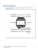
The mechanical diagram shown below outlines the essential details needed to help ensure the correct 
installation of the Controller. 

POWER

STATUS

FAULT

ETHERNET

R1

READER

ZONE

1

2

R2

RELAY

SB SA S- S+

Z2 V- Z1 NC C NO

RS 485 NETWORK 12 VDC OUT

ZONE  2

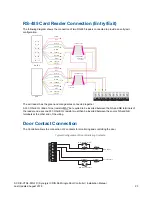
ZONE 1

RELAY 1

ETHERNET

N+ N- NA NB

12VDC IN/OUT RS 485 NETWORK

RS-485 Module Input

12VDC Module Input/Output

Inputs 1 to 2

RS-485 Reader Input

Input Status

Status Indicators

Ethernet Interface

Status Indicators

Relay Output

12VDC Reader Output

BATTERY

POE

POWER

PoE Power / 

Battery Indicators

for PoE models only

B- B+

BATTERY

Battery Backup (PoE models only)


Summary of Contents for Synergis IX

Page 1: ...Synergis IX DIN Rail Single Door Controller SY SIX CTRL DIN 1D Installation Manual...

Page 2: ...state of a product at the time of document s last revision and may not reflect the product at all times in the future In no event shall Genetec be liable to any person or entity with respect to any l...

Page 3: ...dule Network 12 Module Wiring 12 End of Line EOL Resistors 13 Backup Battery 13 Ethernet 10 100 Network Interface 14 Configuration 15 Setting the IP Address 15 Setting the IP Address from a Keypad 15...

Page 4: ...figuration 30 Defaulting a Controller 30 Temporarily Defaulting the IP Address 31 LED Indicators 32 Power Indicator 32 Status Indicator 32 Fault Indicator 32 PoE Power Indicator 33 Battery Indicator 3...

Page 5: ...ork up to a distance of 900M 3000ft Communication beyond this distance requires the use of a RS 485 Network Extender The current features of the Controller include Internal industry standard 10 100 Et...

Page 6: ...ctrical codes These will vary based on country type of distribution system and other factors The integrity of all ground connections should be checked periodically General safety dictates that all met...

Page 7: ...nclosure s DIN Rail Ground Connections multiple cabinets in different rooms sectors or buildings DIN Rail Enclosure Controller Earth Ground Link connection Dialer s Earth Ground Connection Module Netw...

Page 8: ...install the Controller in a location that will facilitate easy access for wiring It is also recommended that the Controller is installed in electrical rooms communication equipment rooms closets or in...

Page 9: ...ile power is applied or the battery is connected may cause serious damage to the unit and will VOID ALL WARRANTIES OR GUARANTEES Power the unit only after all wiring configuration and jumper settings...

Page 10: ...can be used to supply the module network as well so long as the maximum load of the power supply is not exceeded In larger installations the power supply may need to be split to allow for load sharing...

Page 11: ...rnet terminal There are two types of PoE Routers available Low Power Type 1 PoE IEEE 802 3af 12 95W Deliverable High Power Type 2 PoE IEEE 802 3at 25 5W Deliverable When using a PoE Router as the powe...

Page 12: ...upplying the peak current drawn by all modules If a shielded cable is used the shield must be connected at only one end of the cable DO NOT connect a shield at both ends Warning The 12V N and N commun...

Page 13: ...attery in reverse will not damage the Controller but will cause the battery fuse 5A resettable fuse to open requiring the resetting by removal of all connections to the B and B plugs for approximately...

Page 14: ...IP address of 192 168 1 2 with a subnet mask of 255 255 255 0 These IP address settings are commonly used for internal networks Installing the Controller on an active network requires knowledge of th...

Page 15: ...l need to force the Controller into its default state see page 30 Note that this will erase all existing programming as well as setting up the default Installer code 3 Once logged in select Menu 4 Ins...

Page 16: ...is set to 4 for compatibility with older Controller hardware and should be left set to four When the outputs are created they are assigned sequential output numbers 1 to 4 On the Single Door 1D Contr...

Page 17: ...isplayed enabling you to define how the new Controller and associated records will be created Site Copy From Defines the site from which the programming should be copied Controller Copy From Defines t...

Page 18: ...ed by an AC power source AC Fail Time Seconds The AC Failure time allows the installer to program a time that AC mains voltage must have failed before activating the AC Failure Trouble Input Set this...

Page 19: ...primary SNTP server Time Zone The current time zone that should be assigned to the controller Offset from GMT When using a Time Server the time provided is always in UTC Coordinated Universal Time whi...

Page 20: ...r more information about the software configuration 2 Connect the module s that require addressing to the module network Make sure that the Power light on each module is on and that the Status light b...

Page 21: ...een read back from the Controller If the address has not changed check the module is online and communicating and that is has finished attempting to register If the address has changed but the module...

Page 22: ...ld to any shield used for isolated communication All Synergis readers are shipped with single LED mode set as default Reader Location As two RS 485 readers can be connected to the same RS 485 reader p...

Page 23: ...Z2 V Z1 NC C NO RS 485 NETWORK 12VDC OUT ZONE 2 ZONE 1 RELAY 1 VIOLET VIOLET ENTRY EXIT 1 2 3 4 5 6 7 8 9 0 X The exit reader has the green and orange wires connected together A 330 Ohm EOL End of Li...

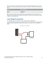
Page 24: ...o operate regardless of the door contact state The REX input can also be programmed to recycle the door alarm time to prevent nuisance alarms when the door is held open to permit longer entry Lock Out...

Page 25: ...address is unique The onboard reader uses inputs 1 and 2 as its door contact and REX respectively If either of these inputs is not configured for use with the onboard reader it may be used as general...

Page 26: ...tion when the state of an input is toggled and generates a tamper alarm condition when a wire fault short circuit or a cut tampered in the line occurs Inputs default to require the EOL resistor config...

Page 27: ...r options are supported on the Controller but not all resistor options are supported on all Synergis field modules Value 1 Value 2 Monitored Status 1k 1k Open Closed Tamper Short 1k No Resistor Open C...

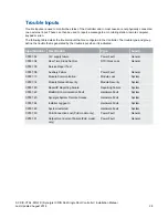
Page 28: ...vated Input Number Description Type Group CP001 02 12V supply failure Power Fault General CP001 04 Real Time Clock Not Set RTC Clock Loss General CP001 05 Service Report Test CP001 08 Auxiliary Failur...

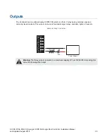
Page 29: ...3 which is a Form C relay having normally open and normally closed contacts This output can be used to activate larger relays sounders lights or locks etc Example Relay Connection LED 1K5 OHM Z2 V Z1...

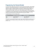
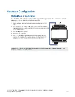
Page 30: ...of the module network and SA of the reader network and between NB of the module network and SB of the reader network 3 Connect Input 1 to ground 4 Power up the Controller 5 Once the Controller has st...

Page 31: ...connect to the web interface to view and or change it 1 Remove power from the Controller by disconnecting the 12V DC input 2 Connect a wire link between NA of the module network and SA of the reader...

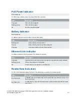
Page 32: ...lied to the Controller Note that this indicator may take several seconds to light up after power has been applied State Description On green Correct input voltage applied Off Incorrect input voltage a...

Page 33: ...battery test On green Last backup battery dynamic test successful Ethernet Link Indicator The Ethernet indicator shows the status of the Ethernet connection State Description On green Valid link with...

Page 34: ...on the Controller is programmed with an input type and area the input status is displayed on the front panel indicators 1 2 corresponding to the physical input number Z1 Z2 This allows easy walk test...

Page 35: ...ER STATUS FAULT ETHERNET R1 READER ZONE 1 2 R2 RELAY SB SA S S Z2 V Z1 NC C NO RS 485 NETWORK 12 VDC OUT ZONE 2 ZONE 1 RELAY 1 ETHERNET N N NA NB 12VDC IN OUT RS 485 NETWORK RS 485 Module Input 12VDC...

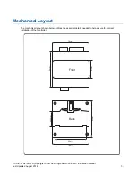
Page 36: ...ntroller Installation Manual Last Updated August 2018 36 Mechanical Layout The mechanical layout shown below outlines the essential details needed to help ensure the correct installation of the Contro...

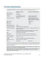
Page 37: ...wing the connection of up to 2 RS 485 capable readers providing entry exit control for a single door Inputs 2 high security monitored inputs Relay Outputs 1 FORM C Relay 7A N O N C at 30 VAC DC resist...

Page 38: ...ngle Door Controller Installation Manual Last Updated August 2018 38 New Zealand and Australia General Product Statement The RCM compliance label indicates that the supplier of the device asserts that...

Page 39: ...s and prevent any potential negative effects on human health and the environment which could otherwise arise from inappropriate waste handling Please contact your local authority for further details o...

Page 40: ...n 30 seconds the entry delay has expired or another instant is violated the main alarm will be triggered and reported To comply with EN 50131 1 neither Internals Only on Part Set Zone Alarm nor Intern...

Page 41: ...ion which can be deter mined by turning the equipment off and on the user is encouraged to try to correct the interference by one or more of the following measures Re orient the receiving antenna Incr...

Page 42: ...or Controller Installation Manual Last Updated August 2018 42 Industry Canada Statement This class A digital apparatus complies with Canadian ICES 003 Cet appareil num rique de la classe A est conform...

Page 43: ...the Genetec Logo are trademarks of Genetec Inc and may be registered or pending registration in several jurisdictions Other trademarks used in this document may be trademarks of the manufacturers or v...

Reviews: