Air Handler
17
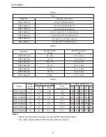
Note:
①
Minimum Circuit Ampacity includes the Blower Motor Full Load Amps
②
Wire size allows for no more than a 2% voltage drop from the building breaker/fuse panel to
the unit.
Refer to the latest edition of the National Electric Code (NEC) in USA or the Canadian Electric
Code (CSA) in Canada when determining the correct wire size. The following table shows the
current carrying capabilities for copper conductors rated at 75ºC with a 2% voltage drop. Use the
Table 14 to determine the voltage drop per foot of various conductors.
Table 14
Maximum Allowable Length in Feet to Limit Voltage Drop to 2% *
Wire
Size(AWG)
Minimum Circuit Ampacity(MCA)
10
15
20
25
30
35
40
45
14
75
50
37
12
118
79
59
47
10
188
125
95
75
63
54
8
301
201
150
120
100
86
75
68
6
471
314
235
188
157
134
118
110
*Based on NEC 2008
4.9.3 Maximum Overcurrent Protection (MOP)
Every installation must include an NEC (USA) or CEC (Canada) approved overcurrent
protection device. Also, check with local or state codes for any special regional requirements.
This protection can be in the form of fusing or HACR style circuit breakers.
Note:
Fuses or circuit breakers are to be sized larger than the equipment MCA but not to
exceed the MOP.
4.9.4 Electric Connections-Supply Voltage
Use Copper Conductors Only
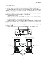
a knockout is provided on the air handler top panel or side to allow for the entry of the supply
voltage conductors. If the knockouts on the cabinet side are used for electrical conduit, an adapter
ring must be used in order to meet UL 1995 safety requirements. An NEC or CEC approved strain
relief is to be used at this entry point. The wire needs to be sized in accordance with the “Wire
Sizing and MOP” section of this manual.
Air Handler Only (Non-Heater Kit Models)
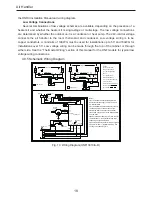
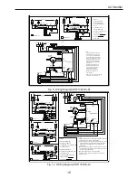
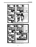
The power cord connects to L1 and L2 terminal located on the electrical box in the air handler.
Note to grounding well. The power cord adopts appropriately sized solderless connector or other
NEC or CEC approved means. Check the unit wiring diagram attached for reference.
Air Handler with Heater Kits (Non-Circuit Breaker)
The power supply should be connected to the stripped black and red wires on the heater kit.
Air Handler with Heater Kits Containing Circuit Breaker
HNRd models with a “B” suffix contain a circuit breaker(s). The air handler has a plastic cover
on the access panel that will require either one or both sections to be removed to allow the heater
kit circuit breaker(s) to be installed. See the HNRd Installation Instruction for further detail. The air
handler wires and supply wires are installed directly onto the HNRd circuit breaker(s) as shown in

