Air Handler
18
the HNRd Installation Manual and wiring diagram.
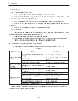
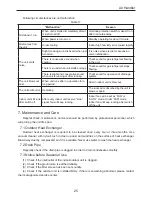
Low Voltage Connections
Several combinations of low voltage schemes are available, depending on the presence of a
heater kit and whether the heater kit is single-stage or multi-stage. The low voltage connections
are determined by whether the outdoor unit is a condenser or heat pump. The 24V-control voltage
connects the air handler to the room thermostat and condenser. Low voltage wiring is to be
copper conductors. A minimum of 18AWG must be used for installations up to 50’ and 16AWG for
installations over 50’. Low voltage wiring can be made through the top of the cabinet or through
either side. See the “Thermostat Wiring” section of this manual for the HNF models for typical low
voltage wiring connections.
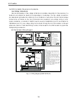
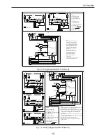
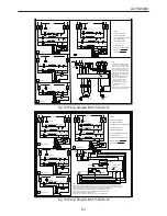
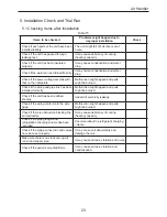
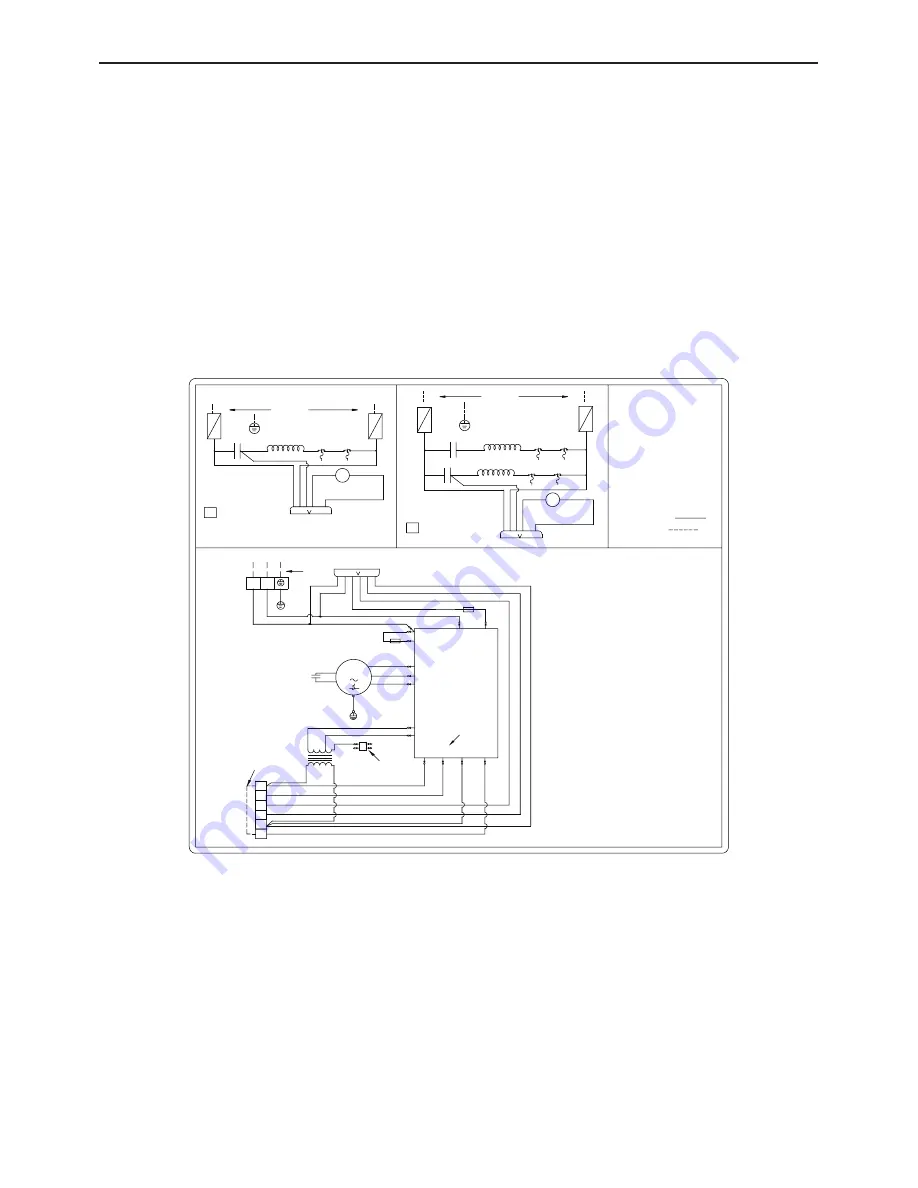
4.9.5 Schematic Wiring Diagram
10kW HEAT KIT
5KW HEAT KIT
HEAT STRIP-2
LS1-2
HS-1
HEAT STRIP-1
LS1-1
HS-1
CB1
CB1
HS-1
LS2-2
LS2-1
44
41
45
42
46
43
SEE NOTE 2
HEAT STRIP-1
LS1-1
HS-1
CB1
CB1
HS-1
LS2-1
41
42
43
SEE NOTE 2
19RD 20W
H
21RD 22RD
24RD
19RD 20W
H
21RD 22RD
24RD
BLOWER
MOTOR
XFMR
YE
WH
1RD
2WH
4RD
5RD
6RD
9RD 10RD 11RD
MAIN BOARD
7RD
8WH
SEE NOTE 1
O
12RD
SEE NOTE 4
SEE NOTE 5
X10
X3(C)
G_SCAN
3RD
X8
AC-L(X1) AC-N(X2)
FU2
RD
BK
1
BU
SEE NOTE 3
X7(N)
X13(L)
X11
FU1
14RD
X14
X6
AC-N(X2)
RD
BN
E
BK(H)
WH
BU(L)
Notes:
1)For Air Handler without installing Electric
Heater,connect the supply power to"L1"and
"L2"terminal block.
2)For Air Handler with Electric Heater, connect
the supply power to circuit breaker.If you
ordered the Heat kit without circuit breaker,
connect the supply power to the stripped black
and red wires.
3)Remove the blue lead from "X7" then connect
the black lead to "X7" terminal for 230 volts,
tape seal the unused blue lead.
4)90 second off delay when "G" is de-energized.
5)Jumper "R" and "o" together if working with
cooling only condensing unit.
LEGEND
CB-CIRCUIT BREAKER
HS-HEAT SEQUENCER
LS1- TEMPERATURE LIMIT
SWITCH
LS2- THERMAL FUSE
XFMR-TRANSFORMER
X1-QUICK CONNECTION PLUG
C-FAN CAPACITOR
XT1/XT2/XT3 TERMINAL BLOCK
FACTORY WIRING:
FIELD WIRING:
BK
BK
BK
BK
34
32
L2
YEGN
G
C
M
POWER
XT2
X1
XT1
13YEGN
3
O_SCAN
G
X9
X4(R)
XT3
6
5
4
2
1
C
W2
W1
G
R
L2
L1
RD
31
BK
BK
BK
BK
32
3
1
6
5
4
3
2
1
X1
RD
RD
33
31
BK
BK
BK
BK
4
3
2
1
6
5
4
3
2
1
X1
G
L2
L1
G
L1
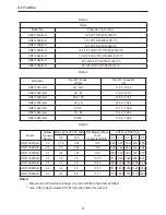
Fig. 10 Wiring Diagram(HNF13018/A-D)

