Section 6 • Schematics
6 - 2
GR-20J • GR-26J
Part No. 227656
September 2016
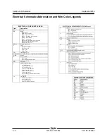
Electrical Schematic Abbreviation and Wire Color Legends
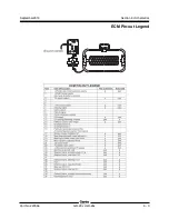
ELECTRICAL COMPONENT LEGEND
Description
Battery
Button
BN
BN5 = Horn
BN8 = Drive enable
BN9 = Lift enable/select
BN57 = Turntable rotate enable
BN63 = Mast enable
BN97 = Jib enable
BN128 = Descend/Rotate left enable
BN129 = Lift/Rotate right enable
BN130 = Drive select
Fuse
F
F6 = Fuse, 250A
F9 = Fuse, 5A
Flashing beacon
Hour meter/Battery charge indicator/Fault code display
Ground
Horn or Alarm
H
H1 = Horn
H2 = Automotive-style horn
Joystick controller
Key switch
LED or Indicator light
L
L4 = Platform overload
L17 = Drive select
L48 = Machine level
L68 = Platform overload
L79 = Out of level
L81 = Mast up-down/turntable rotate
L82 = Jib
Limit switch
LS
LS11 = Jib boom
LS18 = Mast down
LS31 = Platform overload
B9
Item
JC1
KS1
FB1
G6/G7/G8
GND
F9A = Fuse
F9B = Fuse
L1 = Drive enable
LS3 = Drive enable
Parking Brake Relay
CR89
L30 = Work light (Option)


