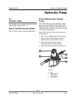
Section 4 • Repair Procedures
4 - 28
GR-20J • GR-26J
Part No. 227656
September 2016
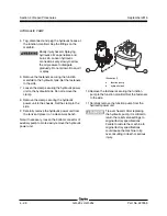
5 Tag, disconnect and plug the hydraulic hoses at
the function manifold. Cap the fittings on the
manifold.
Bodily injury hazard. Spraying
hydraulic oil can penetrate and
burn skin. Loosen hydraulic
connections very slowly to allow
the oil pressure to dissipate
gradually. Do not allow oil to squirt
or spray.
6 Remove the fasteners securing the function
manifold to the hydraulic tank. Set the fasteners
to the side.
7 Loosen the clamp securing the hydraulic power
unit to the hydraulic tank. Do not remove the
clamp.
8 Remove the clamp securing the hydraulic
power unit to the chassis. Set the clamp to the
side.
9 Carefully remove the hydraulic power unit from
the tank and place it on a clean work bench.
Note: If necessary, loosen the bottom connector of
auxiliary pump to more easily remove the hydraulic
power unit.
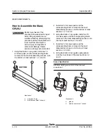
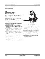
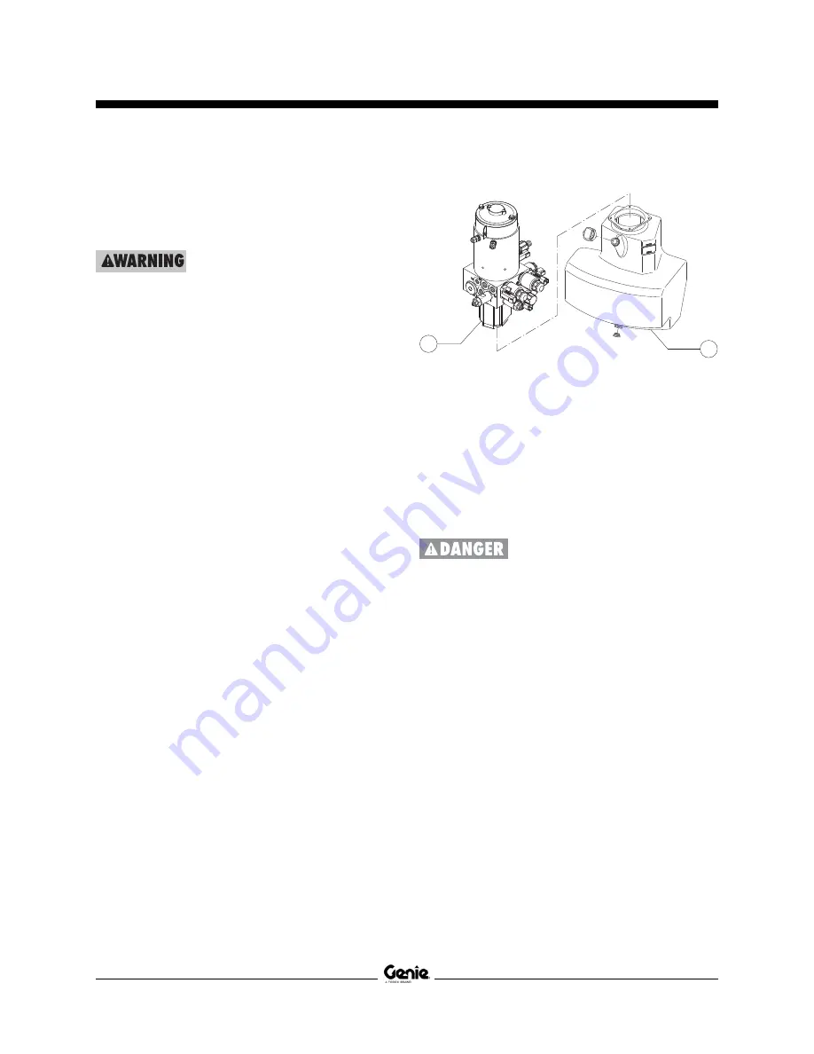
Illustration 2
a
function pump
b
hydraulic tank
10 Remove the fasteners securing the function
pump to the function manifold. Set the fasteners
to the side.
11 Carefully remove the function pump from the
hydraulic power unit.
Tip-over hazard. After replacing
the hydraulic pump, it is critical to
return the relief valve settings to
original factory specifications.
Failure to restore the machine to
original factory specifications
could cause the machine to tip
over, resulting in death or serious
injury.
HYDRAULIC PUMP
a
b

