Section 4 • Repair Procedures
Part No. 227656
GR-20J • GR-26J
4 - 33
September 2016
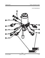
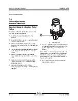
FUNCTION MANIFOLD
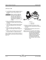
10 Press and hold the jib function button to fully
raise the jib boom, then continue to activate the
jib lift function while observing the pressure
reading on the pressure gauge. Note the
pressure. Refer to Section 2,
Specifications
.
11 Turn the key switch to the off position.
12 Hold the system relief valve with a wrench and
remove the cap.
13 Adjust the internal hex socket. Turn it clockwise
to increase the pressure or counterclockwise to
decrease the pressure. Install the relief valve
cap.
Tip-over hazard. Failure to adjust
the relief valves to specification
could result in the machine tipping
over, causing death or serious
injury. Do not adjust the relief
valve pressures higher than
specifications.
14 Turn the key switch to the ground controls.
15 Repeat this procedure, beginning with step 8, to
confirm the system relief valve pressure.
16 Turn the key switch to the off position.
17 Install and tighten the fasteners securing the
function manifold to the hydraulic tank.
18 Install and securely tighten the hydraulic power
unit clamps. Do not over tighten.


