Section 4 • Repair Procedures
Part No. 227656
GR-20J • GR-26J
4 - 45
September 2016
11 Tag and disconnect the cables from the drive
motor assembly.
12 Loosen the castle nut of the wheel at the
non-steer end of the machine. Do not remove
the castle nut.
Note: To remove the right drive motor assembly,
first it is necessary to remove the left drive motor
assembly.
13 Center a lifting jack under the drive chassis at
the non-steer end of the machine.
14 Raise the machine approximately
6 inches / 15 cm. Place blocks under the
chassis for support. Lower the chassis onto the
blocks.
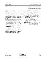
Crushing hazard. The chassis
could fall if not properly supported.
15 Remove the castle nut from the wheel at the
non-steer end of the machine. Remove the
wheel from the machine.
Note: A properly sized puller may be needed to
remove the wheel from the tapered shaft.
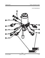
NON-STEER AXLE COMPONENTS
16 Place a 2 x 4 x 6 inch / 5 x 10 x 15 cm long
wood block under the left drive motor.
Note: The wood block will support to the drive
motor assembly when the fasteners are removed.
17 Remove the fasteners securing the left drive
motor assembly to the chassis. Set the
fasteners to the side.
18 Carefully remove the left drive motor assembly
from the machine. Place it onto a suitable
workbench capable of supporting it.
Bodily injury hazard. The
drive motor assembly may fall if
not properly supported when
removed from the machine.

