Section 4 • Repair Procedures
4 - 46
GR-20J • GR-26J
Part No. 227656
September 2016
NON-STEER AXLE COMPONENTS
11-2
Drive Brake
How to Remove the Drive Brake
1 Block the wheels at the steer end of the
machine.
2 Turn the key switch to ground control and pull
out the red Emergency Stop button to the on
position at both the ground and platform
controls.
Note: Rotate the red Emergency Stop button at
platform control one quarter turn in a clockwise
direction to restore the power supply. The red
Emergency Stop button returns automatically to
the out, or on position.
3 Raise the jib boom to the maximum height.
4 Turn the key switch to off position and push in
the red Emergency Stop button to the off
position at the ground control.
5 Open the turntable cover at the ground control
side of the machine.
6 Tag and disconnect the cables from the ground
terminal of the battery.
7 Remove the fasteners securing the rear chassis
cover to the chassis at the non-steer end of the
machine. Remove the chassis cover. Lay the
cover and fasteners to the side.
8 Tag and disconnect the two wire harness
connectors at the steel bar.
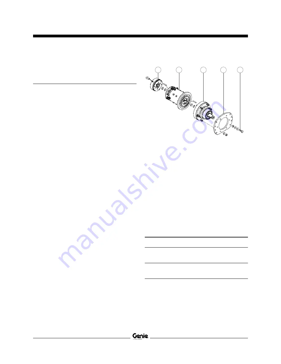
a
b
c
d
e
a
drive brake
b
drive motor assembly
c
speed reducer assembly
d
mounting plate
e
fasteners
9 Remove the fasteners securing the steel bar to
the chassis. Set the fasteners to the side.
10 Turn over the steel bar and cut the zip ties
attaching the two wire harness connectors to
the steel bar. Lay the steel bar to the side.
11 Remove the fasteners securing the drive brake
to the drive motor assembly. Set the fasteners
to the side.
12 Carefully remove the drive brake from the drive
motor assembly.
Torque specifications
Brake mounting fasteners, dry
75 ft-lbs
102 Nm
Brake mounting fasteners, lubricated
56 ft-lbs
76 Nm

