November 2016
Service and Repair Manual
Steer Axle Components
Part No. 1272220GT
GS-2669 DC • GS-3369 DC • GS-4069 DC
73
8-2 St eer Cylinder
8-2
Steer Cylinder
How to Remove the Steer
Cylinder
Note: When removing a hose assembly or fitting,
the O-ring (if equipped) on the fitting and/or hose
end must be replaced. All connections must be
torqued to specification during installation. Refer to
Specifications,
Hydraulic Hose and Fitting Torque
Specifications.
1
Tag, disconnect and plug the hydraulic hoses
from the steer cylinder. Cap the fittings on the
cylinder.
Bodily injury hazard. Spraying
hydraulic oil can penetrate and
burn skin. Loosen hydraulic
connections very slowly to allow
the oil pressure to dissipate
gradually. Do not allow oil to
squirt or spray.
2
Remove the rue ring from each cylinder clevis
pin. Remove the clevis pins.
3
Remove the steer cylinder from the machine.
8-3 Ti e R od
8-3
Tie Rod
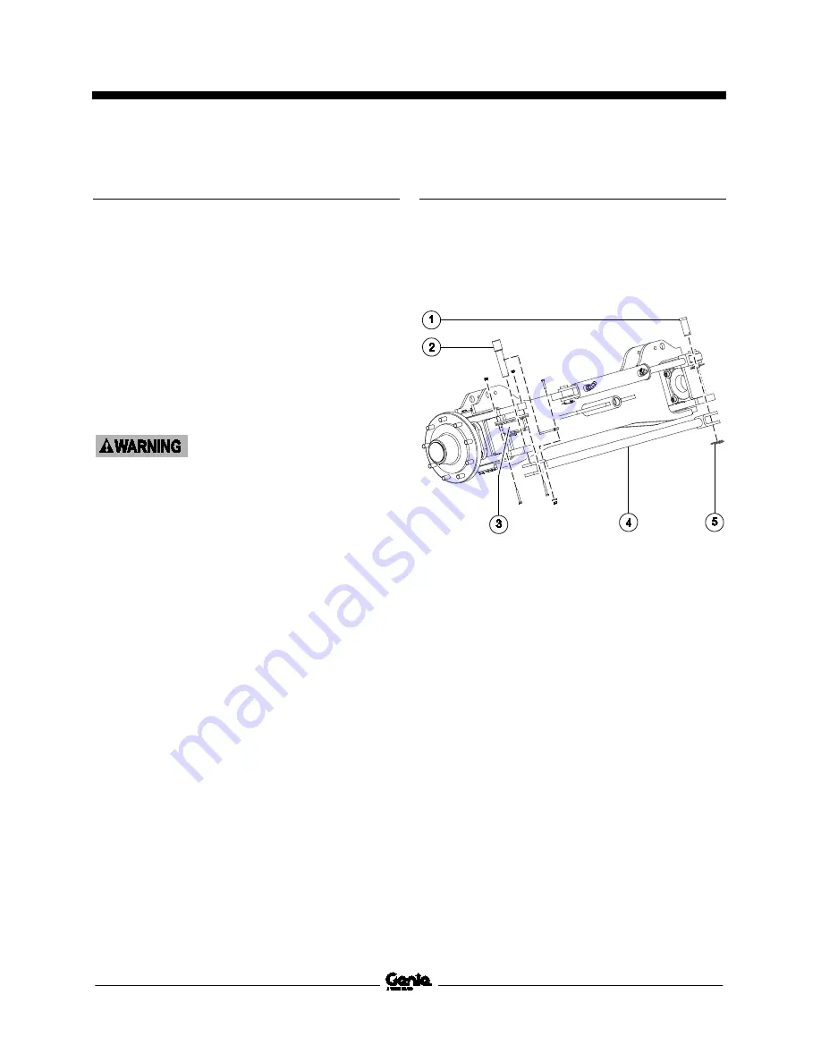
How to Remove the Tie Rod
1
Remove the rue ring from the clevis pin
connecting the tie rod to the right side yoke
assembly. Remove the clevis pin.
1 clevis pin
2 pivot pin
3 steer sensor assembly
4 tie rod
5 rue ring
2
Remove the retaining fasteners from the pivot
pin connecting the tie rod to the left side yoke
assembly.
3
Use a small pry bar to move the pivot pin down
enough to clear the steer sensor assembly.
4
Remove the steer sensor actuator and spring
from the tie rod pivot pin and set aside.
5
Remove the steer sensor assembly and set it
aside.
6
Using a soft metal drift pin and a mallet, drive
the pivot pin up to remove it.
7
Remove the tie rod.


