November 2014
Part No. 229753
GS-2669 RT • GS-3369 RT • GS-4069 RT
Section 4
Repair Procedures
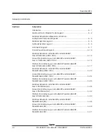
Introduction .................................................................................................. 4 - 1
Platform Controls
1-1
Circuit Boards ..................................................................................... 4 - 2
Platform Components
2-1
Platform .............................................................................................. 4 - 3
2-2
Platform Extension Deck .................................................................... 4 - 4
Scissor Components
3-1
Scissor Assembly, GS-2669 RT ......................................................... 4 - 7
3-2
Scissor Assembly, GS-3369 RT ....................................................... 4 - 11
3-3
Scissor Assembly, GS-4069 RT ....................................................... 4 - 15
3-4
Wear Pads ........................................................................................ 4 - 19
3-5
Lift Cylinder(s) .................................................................................. 4 - 21
Kubota D1105 Engine
4-1
Timing Adjustment ............................................................................ 4 - 23
4-2
Glow Plugs ...................................................................................... 4 - 23
4-3
Engine RPM ..................................................................................... 4 - 24
4-4
Flex Plate ......................................................................................... 4 - 24
4-5
Coolant Temperature and Oil Pressure Switches .............................. 4 - 25
Kubota WG972 Engine
5-1
Timing Adjustment ............................................................................ 4 - 27
5-2
Carburetor Adjustment ...................................................................... 4 - 27
5-3
Choke Adjustment ............................................................................ 4 - 27
5-4
Flex Plate ......................................................................................... 4 - 27
5-5
Coolant Temperature and Oil Pressure Switches .............................. 4 - 27
5-6
Engine RPM ..................................................................................... 4 - 28
xi
TABLE OF CONTENTS
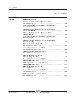
Summary of Contents for GS-2669 RT
Page 169: ...Section 6 Schematics November2014 6 9 Control Panel Circuit Diagram 6 10 ...
Page 235: ...Section 6 Schematics November2014 6 75 6 76 Electrical Schematic GS 4069 RT Gas LPG Models AS ...
Page 238: ...November2014 Section 6 Schematics 6 78 Electrical Schematic GS 4069 RT Gas LPG Models AS 6 77 ...
Page 243: ...Section 6 Schematics November2014 6 83 Electrical Schematic GS 4069 RT Diesel Models AS 6 82 ...
Page 246: ...November2014 Section 6 Schematics 6 86 Electrical Schematic GS 4069 RT Diesel Models AS 6 85 ...
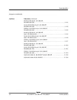
Page 251: ...Section 6 Schematics November2014 6 91 Electrical Schematic GS 4069 RT Gas LPG Models CE 6 92 ...
Page 254: ...November2014 Section 6 Schematics 6 94 Electrical Schematic GS 4069 RT Gas LPG Models CE 6 93 ...
Page 259: ...Section 6 Schematics November2014 6 99 6 100 Electrical Schematic GS 4069 RT Diesel Models CE ...
Page 267: ...Section 6 Schematics November2014 6 107 Hydraulic Schematic GS 2669 RT and GS 3369 RT 6 108 ...
Page 270: ...November2014 Section 6 Schematics 6 110 Hydraulic Schematic GS 4069 RT 6 109 ...


