Section 4 • Repair Procedures
November 2014
Part No. 229753
GS-2669 RT • GS-3369 RT • GS-4069 RT
4 - 45
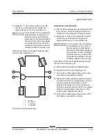
Adjust the front-to-back axis:
13 Without disconnecting the wire harness from the
level sensor, connect the positive lead of the
multimeter to the blue wire at the level sensor.
14 Adjust the "X" axis (front-to-back) to 2.43V DC.
Tap the top of the level sensor lightly with
fingers after each turn of an adjusting nut.
Tip-over hazard. Do not adjust the
potentiometers on the bottom of
the level sensor or calibrate the
level sensor other than specified in
this procedure. Failure to calibrate
the tilt level sensor as instructed
will cause the machine to tip over
resulting in death or serious injury.
Note: Be sure there are threads showing through
the top of each adjusting nut.
15 Disconnect the positive and negative leads.
16 Apply Sentry Seal to the adjusting nuts.
17 Push in the red Emergency Stop button to the
off position at the platform controls.
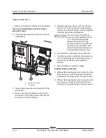
18 Press and hold the auto level button and press
and hold the left front outrigger button. Pull out
the red Emergency Stop button to the on
position at the platform controls. Continue to
hold the auto level button and left front outrigger
button for approximately 3 seconds or until a
beep is heard. Release the buttons.
19 Push in the red Emergency Stop button to the
off position at the platform controls.
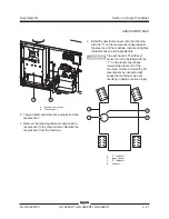
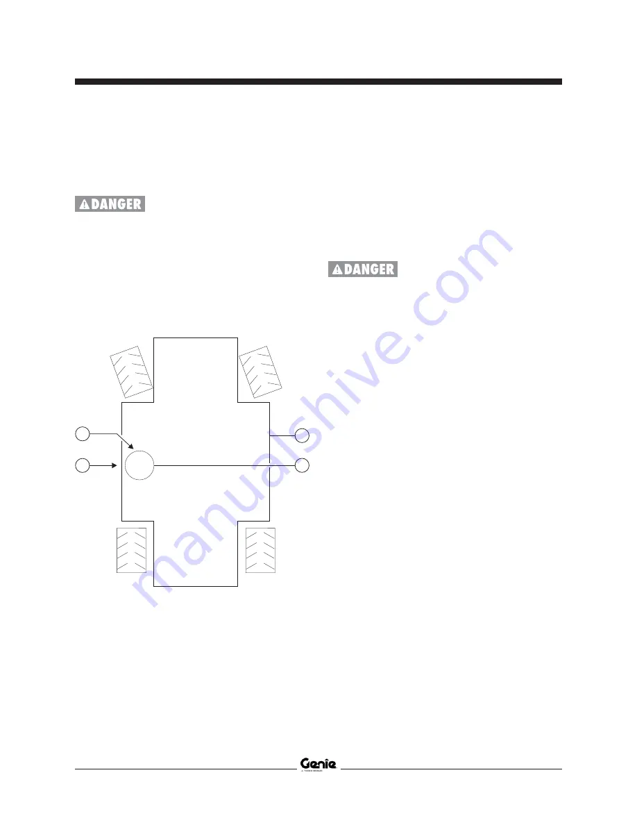
11 Adjust the "Y" axis (side-to-side) to 2.5V DC.
Tap the top of the level sensor lightly with
fingers after each turn of an adjusting nut.
Tip-over hazard. Do not adjust the
potentiometers on the bottom of
the level sensor or calibrate the
level sensor other than specified in
this procedure. Failure to calibrate
the tilt level sensor as instructed
will cause the machine to tip over
resulting in death or serious injury.
Note: Be sure there are threads showing through
the top of each adjusting nut.
a
chassis
b
level sensor
c
"Y" indicator
d
"X" indicator
12 Disconnect the positive lead.
GROUND CONTROLS
Y
X
b
a
c
d
Summary of Contents for GS-2669 RT
Page 169: ...Section 6 Schematics November2014 6 9 Control Panel Circuit Diagram 6 10 ...
Page 235: ...Section 6 Schematics November2014 6 75 6 76 Electrical Schematic GS 4069 RT Gas LPG Models AS ...
Page 238: ...November2014 Section 6 Schematics 6 78 Electrical Schematic GS 4069 RT Gas LPG Models AS 6 77 ...
Page 243: ...Section 6 Schematics November2014 6 83 Electrical Schematic GS 4069 RT Diesel Models AS 6 82 ...
Page 246: ...November2014 Section 6 Schematics 6 86 Electrical Schematic GS 4069 RT Diesel Models AS 6 85 ...
Page 251: ...Section 6 Schematics November2014 6 91 Electrical Schematic GS 4069 RT Gas LPG Models CE 6 92 ...
Page 254: ...November2014 Section 6 Schematics 6 94 Electrical Schematic GS 4069 RT Gas LPG Models CE 6 93 ...
Page 259: ...Section 6 Schematics November2014 6 99 6 100 Electrical Schematic GS 4069 RT Diesel Models CE ...
Page 267: ...Section 6 Schematics November2014 6 107 Hydraulic Schematic GS 2669 RT and GS 3369 RT 6 108 ...
Page 270: ...November2014 Section 6 Schematics 6 110 Hydraulic Schematic GS 4069 RT 6 109 ...

