Section 4 • Repair Procedures
November 2014
Part No. 229753
GS-2669 RT • GS-3369 RT • GS-4069 RT
4 - 47
47 Raise the machine approximately
6 inches / 15 cm.
48 Place a 4.08 x 10 x 10 inch / 10.36 x 25 x 25
cm thick steel block under both wheels at the
non-steer end of the machine.
49 Lower the machine onto the blocks.
50 Raise the platform at least 12 feet / 3.6 m.
Result: The platform stops raising and the tilt
alarm will sound at 180 beeps per minute.
Result: The platform does not stop raising and
the tilt alarm does not sound. The level sensor
must be replaced. Repeat this procedure
beginning with step 2.
Note: For reference only, the output of the level
sensor should be approximately 3.4V DC. To
confirm, connect the positive lead of a multimeter
to the blue wire at the level sensor, and the
negative lead to the black wire.
51 Lower the platform to the stowed position.
52 Raise the machine approximately
6 inches / 15 cm.
53 Remove the blocks from under both wheels.
54 Lower the machine and remove the jack.
55 Turn the key switch to the off position.
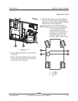
GROUND CONTROLS
Confirm the front-to-back level sensor setting:
37 Center a lifting jack under the drive chassis at
the steer end of the machine.
38 Raise the machine approximately
6 inches / 15 cm.
39 Place a 4.08 x 10 x 10 inch / 10.36 x 25 x 25
cm thick steel block under both wheels at the
steer end of the machine.
40 Lower the machine onto the blocks.
41 Raise the platform at least 12 feet / 3.6 m.
Result: The platform stops raising and the tilt
alarm will sound at 180 beeps per minute.
Result: The platform does not stop raising and
the tilt alarm does not sound. The level sensor
must be replaced. Repeat this procedure
beginning with step 2.
Note: For reference only, the output of the level
sensor should be approximately 1.5V DC. To
confirm, connect the positive lead of a multimeter
to the blue wire at the level sensor, and the
negative lead to the black wire.
42 Lower the platform to the stowed position.
43 Raise the machine approximately
6 inches / 15 cm.
44 Remove the blocks from under both wheels.
45 Lower the machine and remove the jack.
46 Center a lifting jack under the drive chassis at
the non-steer end of the machine.
Summary of Contents for GS-2669 RT
Page 169: ...Section 6 Schematics November2014 6 9 Control Panel Circuit Diagram 6 10 ...
Page 235: ...Section 6 Schematics November2014 6 75 6 76 Electrical Schematic GS 4069 RT Gas LPG Models AS ...
Page 238: ...November2014 Section 6 Schematics 6 78 Electrical Schematic GS 4069 RT Gas LPG Models AS 6 77 ...
Page 243: ...Section 6 Schematics November2014 6 83 Electrical Schematic GS 4069 RT Diesel Models AS 6 82 ...
Page 246: ...November2014 Section 6 Schematics 6 86 Electrical Schematic GS 4069 RT Diesel Models AS 6 85 ...
Page 251: ...Section 6 Schematics November2014 6 91 Electrical Schematic GS 4069 RT Gas LPG Models CE 6 92 ...
Page 254: ...November2014 Section 6 Schematics 6 94 Electrical Schematic GS 4069 RT Gas LPG Models CE 6 93 ...
Page 259: ...Section 6 Schematics November2014 6 99 6 100 Electrical Schematic GS 4069 RT Diesel Models CE ...
Page 267: ...Section 6 Schematics November2014 6 107 Hydraulic Schematic GS 2669 RT and GS 3369 RT 6 108 ...
Page 270: ...November2014 Section 6 Schematics 6 110 Hydraulic Schematic GS 4069 RT 6 109 ...


