Section 4 • Repair Procedures
November 2014
4 - 60
GS-2669 RT • GS-3369 RT • GS-4069 RT
Part No. 229753
MANIFOLDS
9-4
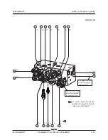
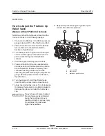
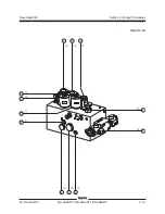
Traction Manifold Components - View 1
The
traction manifold is located inside the ground control box.
Index
Schematic
No.
Description
Item
Function
Torque
1
Solenoid valve, 2 position 3 way ........ TA ....... Brake release ................................... 15-20 ft-lbs / 20-27 Nm
2
Solenoid valve, 2 position 4 way ........ TB ....... Front motor isolate ............................ 20-25 ft-lbs / 27-34 Nm
3
Relief valve, 2500 psi / 172.4 bar ....... TC ....... Drive pressure circuit ........................ 15-20 ft-lbs / 20-27 Nm
4
Needle valve N.C. ............................... TD ....... Enables towing ability ...................... 20-25 ft-lbs / 27-34 Nm
5
Solenoid valve, 3 position 4 way ........ TE ....... Drive forward / reverse ..................... 20-25 ft-lbs / 27-34 Nm
6
Orifice, 0.060 inch / 1.5 mm ................. TF ....... Equalizes pressure on both sides
of flow divider/combiner valve 17
7
Flow divider/combiner valve ............... TG ....... Controls flow to flow
divider/combiner valves
8 and 17 .......................................... 73-77 ft-lbs / 99-104 Nm
8
Flow divider/combiner valve ............... TH ....... Controls flow to steer end
drive motors in forward
and reverse ....................................... 48-52 ft-lbs / 65-71 Nm
9
Orifice, 0.060 inch / 1.5 mm ................. TI ......... Equalizes pressure on both sides
of flow divider/combiner valve 8
10
Solenoid valve, 2 position 2 way ........ TJ ........ Allows flow to bypass
divider/combiner valve 7
in high drive ...................................... 20-25 ft-lbs / 27-34 Nm
11
Solenoid valve, 2 position 2 way ....... TK ........ Allows flow to loop the steer end
motors in high drive .......................... 20-25 ft-lbs / 27-34 Nm
12
Solenoid valve, 2 position 3 way ........ TL ....... Two speed circuit .............................. 15-20 ft-lbs / 20-27 Nm
This list continues. Please turn the page.
Summary of Contents for GS-2669 RT
Page 169: ...Section 6 Schematics November2014 6 9 Control Panel Circuit Diagram 6 10 ...
Page 235: ...Section 6 Schematics November2014 6 75 6 76 Electrical Schematic GS 4069 RT Gas LPG Models AS ...
Page 238: ...November2014 Section 6 Schematics 6 78 Electrical Schematic GS 4069 RT Gas LPG Models AS 6 77 ...
Page 243: ...Section 6 Schematics November2014 6 83 Electrical Schematic GS 4069 RT Diesel Models AS 6 82 ...
Page 246: ...November2014 Section 6 Schematics 6 86 Electrical Schematic GS 4069 RT Diesel Models AS 6 85 ...
Page 251: ...Section 6 Schematics November2014 6 91 Electrical Schematic GS 4069 RT Gas LPG Models CE 6 92 ...
Page 254: ...November2014 Section 6 Schematics 6 94 Electrical Schematic GS 4069 RT Gas LPG Models CE 6 93 ...
Page 259: ...Section 6 Schematics November2014 6 99 6 100 Electrical Schematic GS 4069 RT Diesel Models CE ...
Page 267: ...Section 6 Schematics November2014 6 107 Hydraulic Schematic GS 2669 RT and GS 3369 RT 6 108 ...
Page 270: ...November2014 Section 6 Schematics 6 110 Hydraulic Schematic GS 4069 RT 6 109 ...

