Section 4 • Repair Procedures
November 2014
Part No. 229753
GS-2669 RT • GS-3369 RT • GS-4069 RT
4 - 67
MANIFOLDS
How to Test the Coils Using the
Test System Function
The Electronic Control Module (ECM) contains
programming that can test the coils on the function
and traction manifolds. If a fault is detected it will
show in the diagnostic display window.
Note: Perform this procedure on a flat level surface
and the platform in the stowed position.
1 Pull out the red Emergency Stop button to the
on position at the platform controls.
2 Push in the red Emergency Stop button to the
off position at the ground controls.
3 Turn the key switch to ground control.
4 Press and hold both the blue platform up and
yellow platform down buttons. Pull out the red
Emergency Stop button to the on position at the
ground controls.
Result:
TUNE
SPEEDS
is showing in the diagnostic
display window.
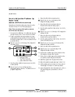
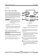
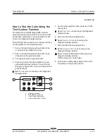
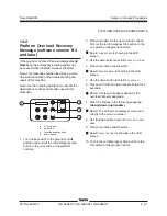
a
diagnostic display
b
blue platform up button
c
lift function enable button
d
yellow platform down button
5 Use the yellow platform down arrow to scroll to
test system.
Result:
TEST
SYSTEM
is showing in the diagnostic
display window.
6 Press the lift function enable button.
Result:
RUN
SYSTEM
TEST
is showing in the
diagnostic display window.
7 Press the lift function enable button.
Result:
NO
FAULTS
DETECTED
is showing in the
diagnostic display window.
Result: A fault is detected and showing in the
diagnostic display window.
Refer to
Section 5, Fault Codes
.
8 Push in the red Emergency Stop button to the
off position at the ground controls.
b
c
d
a
Summary of Contents for GS-2669 RT
Page 169: ...Section 6 Schematics November2014 6 9 Control Panel Circuit Diagram 6 10 ...
Page 235: ...Section 6 Schematics November2014 6 75 6 76 Electrical Schematic GS 4069 RT Gas LPG Models AS ...
Page 238: ...November2014 Section 6 Schematics 6 78 Electrical Schematic GS 4069 RT Gas LPG Models AS 6 77 ...
Page 243: ...Section 6 Schematics November2014 6 83 Electrical Schematic GS 4069 RT Diesel Models AS 6 82 ...
Page 246: ...November2014 Section 6 Schematics 6 86 Electrical Schematic GS 4069 RT Diesel Models AS 6 85 ...
Page 251: ...Section 6 Schematics November2014 6 91 Electrical Schematic GS 4069 RT Gas LPG Models CE 6 92 ...
Page 254: ...November2014 Section 6 Schematics 6 94 Electrical Schematic GS 4069 RT Gas LPG Models CE 6 93 ...
Page 259: ...Section 6 Schematics November2014 6 99 6 100 Electrical Schematic GS 4069 RT Diesel Models CE ...
Page 267: ...Section 6 Schematics November2014 6 107 Hydraulic Schematic GS 2669 RT and GS 3369 RT 6 108 ...
Page 270: ...November2014 Section 6 Schematics 6 110 Hydraulic Schematic GS 4069 RT 6 109 ...


