Section 3 • Scheduled Maintenance Procedures
November 2014
Part No. 229753
GS-2669 RT • GS-3369 RT • GS-4069 RT
3 - 9
A-4
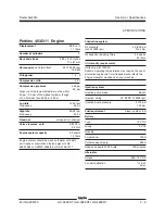
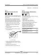
Perform Engine Maintenance
Engine specifications require that this procedure be
performed every 8 hours or daily, whichever comes
first.
• Check oil level
• Check radiator level
• Oil or coolant leaks
• Loose or missing fasteners
Required maintenance procedures and additional
engine information is available in the
Kubota D1105 Operator's Manual
(Kubota part number 16622-89166) OR the
Kubota WG972 Operator's Manual
(Kubota part number EG801-8916-2) OR the
Perkins 403D-11 Operator's Manual
(Perkins part number SEBU8311-01).
Kubota D1105 Operator's Manual
Genie part number
131379
Kubota WG972 Operator's Manual
Genie part number
234803
Perkins 403D-11 Operator's Manual
Genie part number
131661
A-5
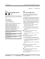
Test the Oscillate Axle
Note: Genie specifications require that this
procedure be performed daily or every 8 hours,
whichever comes first.
The oscillate system is designed so that all four
tires maintain firm contact to the ground on unlevel
terrain improving traction and machine stability.
Proper axle oscillation is essential to safe machine
operation. If the axle oscillation system is not
operating correctly, the stability of the machine is
compromised and it may tip over.
1 Start the engine from the platform controls.
Select the high idle function.
Test the Oscillate System (stowed position):
2 Drive the left steer tire up onto a 4 in / 10 cm
high ramp.
Result: All four tires should maintain firm
contact with the ground.
3 Drive the right steer tire up onto a 4 in / 10 cm
high ramp.
Result: All four tires should maintain firm
contact with the ground.
Test the Oscillate System (elevated position):
4 Push and hold the lift function enable button and
raise the platform between 7 ft / 213 cm to
9 ft / 274 cm.
5 Drive the left steer tire into a 4 in / 10 cm deep
hole.
Result: All four tires should maintain firm
contact with the ground.
6 Drive the right steer tire into a 4 in / 10 cm deep
hole.
Result: All four tires should maintain firm
contact with the ground.
Note: Verify there are no fault codes shown on the
ground control display.
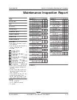
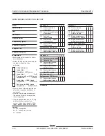
CHECKLIST
A
PROCEDURES
Summary of Contents for GS-2669 RT
Page 169: ...Section 6 Schematics November2014 6 9 Control Panel Circuit Diagram 6 10 ...
Page 235: ...Section 6 Schematics November2014 6 75 6 76 Electrical Schematic GS 4069 RT Gas LPG Models AS ...
Page 238: ...November2014 Section 6 Schematics 6 78 Electrical Schematic GS 4069 RT Gas LPG Models AS 6 77 ...
Page 243: ...Section 6 Schematics November2014 6 83 Electrical Schematic GS 4069 RT Diesel Models AS 6 82 ...
Page 246: ...November2014 Section 6 Schematics 6 86 Electrical Schematic GS 4069 RT Diesel Models AS 6 85 ...
Page 251: ...Section 6 Schematics November2014 6 91 Electrical Schematic GS 4069 RT Gas LPG Models CE 6 92 ...
Page 254: ...November2014 Section 6 Schematics 6 94 Electrical Schematic GS 4069 RT Gas LPG Models CE 6 93 ...
Page 259: ...Section 6 Schematics November2014 6 99 6 100 Electrical Schematic GS 4069 RT Diesel Models CE ...
Page 267: ...Section 6 Schematics November2014 6 107 Hydraulic Schematic GS 2669 RT and GS 3369 RT 6 108 ...
Page 270: ...November2014 Section 6 Schematics 6 110 Hydraulic Schematic GS 4069 RT 6 109 ...


