Section 3 • Scheduled Maintenance Procedures
November 2014
Part No. 229753
GS-2669 RT • GS-3369 RT • GS-4069 RT
3 - 15
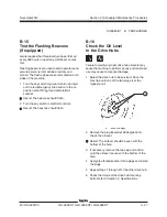
Bleed the fuel system:
Note: Before bleeding the system, fill the fuel tank.
5 Loosen the vent plug/screw located on the filter
head.
6 Operate the hand primer until fuel, free of air,
flows from the vent plug/screw. Tighten the vent
plug/screw on the filter head.
7 Loosen the vent screw, located on top of the
fuel injection pump.
8 Operate the hand primer until fuel, free of air,
flows from the vent plug/screw. Tighten the vent
plug/screw on the injection pump.
9 Clean up any fuel that may have spilled.
10 Attempt to start the engine using the starter
motor for a maximum of 15 seconds, resting the
starter for 30 seconds before trying again.
11 Inspect the fuel filter/water separator for leaks.
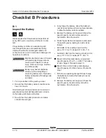
Explosion and fire hazard. If a fuel
leak is discovered, keep any
additional personnel from entering
the area and do not operate the
machine. Repair the leak
immediately.
Note: Information to perform this procedure is also
available in the
Kubota D1105 Operator's Manual
(Kubota part number 16622-89166) OR the
Kubota D1105 Operator's Manual
Genie part number
131379
CHECKLIST
A
PROCEDURES
A-14
Perform Engine Maintenance -
Kubota Diesel Models
Engine specifications require that this procedure be
performed every one or two months.
• Recharge battery
Required maintenance procedures and additional
engine information is available in the
Kubota D1105 Operator's Manual
(Kubota part number 16622-89166).
Kubota D1105 Operator's Manual
Genie part number
131379
Summary of Contents for GS-2669 RT
Page 169: ...Section 6 Schematics November2014 6 9 Control Panel Circuit Diagram 6 10 ...
Page 235: ...Section 6 Schematics November2014 6 75 6 76 Electrical Schematic GS 4069 RT Gas LPG Models AS ...
Page 238: ...November2014 Section 6 Schematics 6 78 Electrical Schematic GS 4069 RT Gas LPG Models AS 6 77 ...
Page 243: ...Section 6 Schematics November2014 6 83 Electrical Schematic GS 4069 RT Diesel Models AS 6 82 ...
Page 246: ...November2014 Section 6 Schematics 6 86 Electrical Schematic GS 4069 RT Diesel Models AS 6 85 ...
Page 251: ...Section 6 Schematics November2014 6 91 Electrical Schematic GS 4069 RT Gas LPG Models CE 6 92 ...
Page 254: ...November2014 Section 6 Schematics 6 94 Electrical Schematic GS 4069 RT Gas LPG Models CE 6 93 ...
Page 259: ...Section 6 Schematics November2014 6 99 6 100 Electrical Schematic GS 4069 RT Diesel Models CE ...
Page 267: ...Section 6 Schematics November2014 6 107 Hydraulic Schematic GS 2669 RT and GS 3369 RT 6 108 ...
Page 270: ...November2014 Section 6 Schematics 6 110 Hydraulic Schematic GS 4069 RT 6 109 ...

