Section 3 • Scheduled Maintenance Procedures
November 2014
3 - 20
GS-2669 RT • GS-3369 RT • GS-4069 RT
Part No. 229753
B-6
Test the Emergency Stop
Genie requires that this procedure be performed
every 250 hours or quarterly, whichever comes
first.
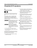
A properly functioning Emergency Stop is essential
for safe machine operation. An improperly
operating red Emergency Stop button
will fail to shut off power and stop all machine
functions, resulting in a hazardous situation.
Note: As a safety feature, selecting and operating
the ground controls will override the platform
controls, except the platform red Emergency Stop
button.
1 Start the engine from ground controls.
2 Push in the red Emergency Stop button to the
off position.
Result: The engine should shut off and no
machine functions should operate.
3 Start the engine from platform controls.
4 Push in the red Emergency Stop button to the
off position.
Result: The engine should shut off and no
machine functions should operate.
Note: The red Emergency Stop button at the ground
controls should stop all machine operation, even if
the key switch is switched to platform control.
CHECKLIST
B
PROCEDURES
B-7
Test the Automotive-style Horn
Genie requires that this procedure be performed
every 250 hours or quarterly, whichever comes
first.
A functioning horn is essential to safe machine
operation. The horn is activated at the platform
controls and sounds at the ground as a warning to
ground personnel. An improperly functioning horn
will prevent the operator from alerting ground
personnel of hazards or unsafe conditions.
1 Turn the key switch to platform control and
pull out the red Emergency Stop button to the
ON
position at both the ground and platform
controls.
2 Push down the horn button at the platform
controls.
Result: The horn should sound.
Note: If necessary, the horn can be adjusted to
obtain the loudest volume by turning the
adjustment screw near the wire terminals on the
horn.
Summary of Contents for GS-2669 RT
Page 169: ...Section 6 Schematics November2014 6 9 Control Panel Circuit Diagram 6 10 ...
Page 235: ...Section 6 Schematics November2014 6 75 6 76 Electrical Schematic GS 4069 RT Gas LPG Models AS ...
Page 238: ...November2014 Section 6 Schematics 6 78 Electrical Schematic GS 4069 RT Gas LPG Models AS 6 77 ...
Page 243: ...Section 6 Schematics November2014 6 83 Electrical Schematic GS 4069 RT Diesel Models AS 6 82 ...
Page 246: ...November2014 Section 6 Schematics 6 86 Electrical Schematic GS 4069 RT Diesel Models AS 6 85 ...
Page 251: ...Section 6 Schematics November2014 6 91 Electrical Schematic GS 4069 RT Gas LPG Models CE 6 92 ...
Page 254: ...November2014 Section 6 Schematics 6 94 Electrical Schematic GS 4069 RT Gas LPG Models CE 6 93 ...
Page 259: ...Section 6 Schematics November2014 6 99 6 100 Electrical Schematic GS 4069 RT Diesel Models CE ...
Page 267: ...Section 6 Schematics November2014 6 107 Hydraulic Schematic GS 2669 RT and GS 3369 RT 6 108 ...
Page 270: ...November2014 Section 6 Schematics 6 110 Hydraulic Schematic GS 4069 RT 6 109 ...

