Section 3 • Scheduled Maintenance Procedures
November 2014
Part No. 229753
GS-2669 RT • GS-3369 RT • GS-4069 RT
3 - 27
CHECKLIST
B
PROCEDURES
B-15
Test the Flashing Beacons
(if equipped)
Genie requires that this procedure be performed
every 250 hours or quarterly, whichever comes
first.
Flashing beacons are used to alert operators and
ground personnel of machine proximity and
motion. The flashing beacons are located on both
sides of the machine.
1 Turn the key switch to ground control and pull
out the red Emergency Stop button to the on
position at both the ground and platform
controls.
Result: The beacons should flash.
2 Turn the key switch to platform controls.
Result: The beacons should flash.
B-16
Check the Oil Level
in the Drive Hubs
Failure to maintain proper drive hub oil levels may
cause the machine to perform poorly and continued
use may cause component damage.
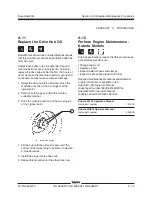
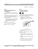
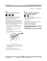
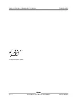
1 Select the drive hub to be serviced. Drive the
machine until one of the two plugs is at the
highest point.
a
drive hub plugs
2 Remove the plug located at 90 degrees and
check the oil level.
Result: The oil level should be even with the
bottom of the hole.
3 If necessary, remove the top plug and add oil
until the oil level is even with the bottom of the
hole.
4 Apply pipe thread sealant to the plugs and install
the plugs.
5 Repeat steps 1 through 4 for the other drive hub.
6 Check the torque of the drive hub mounting
bolts. Refer to Section 2,
Specifications
.
a
Summary of Contents for GS-2669 RT
Page 169: ...Section 6 Schematics November2014 6 9 Control Panel Circuit Diagram 6 10 ...
Page 235: ...Section 6 Schematics November2014 6 75 6 76 Electrical Schematic GS 4069 RT Gas LPG Models AS ...
Page 238: ...November2014 Section 6 Schematics 6 78 Electrical Schematic GS 4069 RT Gas LPG Models AS 6 77 ...
Page 243: ...Section 6 Schematics November2014 6 83 Electrical Schematic GS 4069 RT Diesel Models AS 6 82 ...
Page 246: ...November2014 Section 6 Schematics 6 86 Electrical Schematic GS 4069 RT Diesel Models AS 6 85 ...
Page 251: ...Section 6 Schematics November2014 6 91 Electrical Schematic GS 4069 RT Gas LPG Models CE 6 92 ...
Page 254: ...November2014 Section 6 Schematics 6 94 Electrical Schematic GS 4069 RT Gas LPG Models CE 6 93 ...
Page 259: ...Section 6 Schematics November2014 6 99 6 100 Electrical Schematic GS 4069 RT Diesel Models CE ...
Page 267: ...Section 6 Schematics November2014 6 107 Hydraulic Schematic GS 2669 RT and GS 3369 RT 6 108 ...
Page 270: ...November2014 Section 6 Schematics 6 110 Hydraulic Schematic GS 4069 RT 6 109 ...

