Section 3 • Scheduled Maintenance Procedures
November 2014
3 - 34
GS-2669 RT • GS-3369 RT • GS-4069 RT
Part No. 229753
Checklist D Procedures
D-1
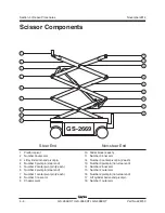
Check the Scissor Arm Wear
Pads and Slider Blocks
Genie requires that this procedure be performed
every 1000 hours or annually, whichever comes
first.
Maintaining the scissor arm wear pads in good
condition is essential to safe machine operation.
Continued use of worn out wear pads may result in
component damage and unsafe operating
conditions.
1 Measure the thickness of each platform scissor
arm slider blocks at the non-steer end of the
machine.
Result: The measurement is 3.875 inch /
9.843 cm or more. Proceed to step 2.
Result: The measurement is less than
3.875 inch / 9.843 cm. Replace both slider
blocks.
2 Measure the thickness of each chassis scissor
arm upper and lower slider wear pads at the
non-steer end of the machine.
Result: The measurement is
1
/
4
inch / 6.35 mm
or more. Proceed to step 3.
Result: The measurement is less than
11
/
32
inch / 8.71 mm. Replace both upper and
lower slider wear pads.
D-2
Replace the Hydraulic Tank
Return Filter
Genie requires that this procedure be performed
every 1000 hours or annually, whichever comes
first.
Replacement of the hydraulic tank return filter is
essential for good machine performance and
service life. A dirty or clogged filter may cause the
machine to perform poorly and continued use may
cause component damage. Extremely dirty
conditions may require that the filter be replaced
more often.
Bodily injury hazard. Beware of hot
oil. Contact with hot oil may cause
severe burns.
1 Remove the filter with an oil filter wrench. Clean
the area where the hydraulic oil filter meets the
filter head.
Bodily injury hazard. Spraying
hydraulic oil can penetrate and
burn skin. Loosen hydraulic
connections very slowly to allow
the oil pressure to dissipate
gradually. Do not allow oil to squirt
or spray.
Note: The hydraulic filter is mounted on the
hydraulic tank.
Summary of Contents for GS-2669 RT
Page 169: ...Section 6 Schematics November2014 6 9 Control Panel Circuit Diagram 6 10 ...
Page 235: ...Section 6 Schematics November2014 6 75 6 76 Electrical Schematic GS 4069 RT Gas LPG Models AS ...
Page 238: ...November2014 Section 6 Schematics 6 78 Electrical Schematic GS 4069 RT Gas LPG Models AS 6 77 ...
Page 243: ...Section 6 Schematics November2014 6 83 Electrical Schematic GS 4069 RT Diesel Models AS 6 82 ...
Page 246: ...November2014 Section 6 Schematics 6 86 Electrical Schematic GS 4069 RT Diesel Models AS 6 85 ...
Page 251: ...Section 6 Schematics November2014 6 91 Electrical Schematic GS 4069 RT Gas LPG Models CE 6 92 ...
Page 254: ...November2014 Section 6 Schematics 6 94 Electrical Schematic GS 4069 RT Gas LPG Models CE 6 93 ...
Page 259: ...Section 6 Schematics November2014 6 99 6 100 Electrical Schematic GS 4069 RT Diesel Models CE ...
Page 267: ...Section 6 Schematics November2014 6 107 Hydraulic Schematic GS 2669 RT and GS 3369 RT 6 108 ...
Page 270: ...November2014 Section 6 Schematics 6 110 Hydraulic Schematic GS 4069 RT 6 109 ...


