Section 3 • Scheduled Maintenance Procedures
November 2014
Part No. 229753
GS-2669 RT • GS-3369 RT • GS-4069 RT
3 - 35
CHECKLIST
D
PROCEDURES
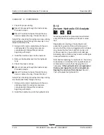
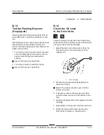
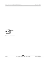
2 Apply a thin layer of fresh oil to the new oil filter
gasket.
3 Install the new filter and tighten it securely by
hand.
4 Use a permanent ink marker to write the date
and number of hours from the hour meter on
the filter.
5 Clean up any oil that may have spilled during
the replacement procedure.
6 Turn the key switch to ground controls and pull
out the red Emergency Stop button to the on
position at both the ground and platform
controls. Start the engine.
7 Raise the platform approximately 3 feet / 1 m.
8 Inspect the filter and related components to
be sure that there are no leaks.
D-3
Perform Engine Maintenance -
Kubota Models
Engine specifications require that this procedure be
performed annually.
Kubota D1105:
• Replace air filter
Kubota WG972:
• Replace air filter
• Replace fuel lines and clamps
• Clean carburetor
Required maintenance procedures and additional
engine information is available in the
Kubota D1105 Operator's Manual
(Kubota part number 16622-89166) OR the
Kubota WG972 Operator's Manual
(Kubota part number EG801-8916-2).
Kubota D1105 Operator's Manual
Genie part number
131379
Kubota WG972 Operator's Manual
Genie part number
234803
Summary of Contents for GS-2669 RT
Page 169: ...Section 6 Schematics November2014 6 9 Control Panel Circuit Diagram 6 10 ...
Page 235: ...Section 6 Schematics November2014 6 75 6 76 Electrical Schematic GS 4069 RT Gas LPG Models AS ...
Page 238: ...November2014 Section 6 Schematics 6 78 Electrical Schematic GS 4069 RT Gas LPG Models AS 6 77 ...
Page 243: ...Section 6 Schematics November2014 6 83 Electrical Schematic GS 4069 RT Diesel Models AS 6 82 ...
Page 246: ...November2014 Section 6 Schematics 6 86 Electrical Schematic GS 4069 RT Diesel Models AS 6 85 ...
Page 251: ...Section 6 Schematics November2014 6 91 Electrical Schematic GS 4069 RT Gas LPG Models CE 6 92 ...
Page 254: ...November2014 Section 6 Schematics 6 94 Electrical Schematic GS 4069 RT Gas LPG Models CE 6 93 ...
Page 259: ...Section 6 Schematics November2014 6 99 6 100 Electrical Schematic GS 4069 RT Diesel Models CE ...
Page 267: ...Section 6 Schematics November2014 6 107 Hydraulic Schematic GS 2669 RT and GS 3369 RT 6 108 ...
Page 270: ...November2014 Section 6 Schematics 6 110 Hydraulic Schematic GS 4069 RT 6 109 ...


