November 2014
Part No. 229753
GS-2669 RT • GS-3369 RT • GS-4069 RT
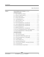
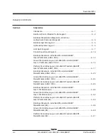
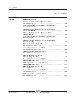
TABLE OF CONTENTS
Section 3
Scheduled Maintenance Procedures
, continued
Checklist A Procedures
A-1
Inspect the Manuals and Decals ......................................................... 3 - 7
A-2
Perform Pre-operation Inspection ........................................................ 3 - 8
A-3
Perform Function Tests ...................................................................... 3 - 8
A-4
Perform Engine Maintenance .............................................................. 3 - 9
A-5
Test the Oscillate Axle ....................................................................... 3 - 9
A-6
Inspect the Engine Air Filter .............................................................. 3 - 10
A-7
Perform 30 Day Service .................................................................... 3 - 11
A-8
Perform Engine Maintenance - Kubota Models .................................. 3 - 11
A-9
Perform Engine Maintenance - Kubota Models .................................. 3 - 12
A-10 Perform Engine Maintenance - Kubota Models .................................. 3 - 12
A-11 Replace the Drive Hub Oil ................................................................. 3 - 13
A-12 Perform Engine Maintenance - Kubota Models .................................. 3 - 13
A-13 Drain the Fuel Filter/Water Separator - Kubota Diesel Models ........... 3 - 14
A-14 Perform Engine Maintenance - Kubota Diesel Models ....................... 3 - 15
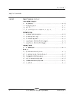
Checklist B Procedures
B-1
Inspect the Battery ........................................................................... 3 - 16
B-2
Inspect the Electrical Wiring ............................................................. 3 - 17
B-3
Inspect the Tires, Wheels and Lug Bolt Torque ................................. 3 - 18
B-4
Perform Engine Maintenance - Perkins Models ................................. 3 - 19
B-5
Test the Key Switch ......................................................................... 3 - 19
B-6
Test the Emergency Stop ................................................................. 3 - 20
B-7
Test the Automotive-style Horn ......................................................... 3 - 20
B-8
Test the Fuel Select Operation - Kubota Gas/LPG Models ............... 3 - 21
B-9
Test the Drive Brakes ....................................................................... 3 - 22
B-10 Test the Drive Speed - Stowed Position ............................................ 3 - 23
ix
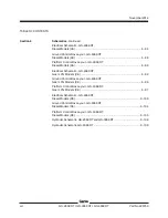
Summary of Contents for GS-2669 RT
Page 169: ...Section 6 Schematics November2014 6 9 Control Panel Circuit Diagram 6 10 ...
Page 235: ...Section 6 Schematics November2014 6 75 6 76 Electrical Schematic GS 4069 RT Gas LPG Models AS ...
Page 238: ...November2014 Section 6 Schematics 6 78 Electrical Schematic GS 4069 RT Gas LPG Models AS 6 77 ...
Page 243: ...Section 6 Schematics November2014 6 83 Electrical Schematic GS 4069 RT Diesel Models AS 6 82 ...
Page 246: ...November2014 Section 6 Schematics 6 86 Electrical Schematic GS 4069 RT Diesel Models AS 6 85 ...
Page 251: ...Section 6 Schematics November2014 6 91 Electrical Schematic GS 4069 RT Gas LPG Models CE 6 92 ...
Page 254: ...November2014 Section 6 Schematics 6 94 Electrical Schematic GS 4069 RT Gas LPG Models CE 6 93 ...
Page 259: ...Section 6 Schematics November2014 6 99 6 100 Electrical Schematic GS 4069 RT Diesel Models CE ...
Page 267: ...Section 6 Schematics November2014 6 107 Hydraulic Schematic GS 2669 RT and GS 3369 RT 6 108 ...
Page 270: ...November2014 Section 6 Schematics 6 110 Hydraulic Schematic GS 4069 RT 6 109 ...


