Section 4 • Repair Procedures
November 2014
Part No. 229753
GS-2669 RT • GS-3369 RT • GS-4069 RT
4 - 23
Kubota D1105 Engine
4-1
Timing Adjustment
Complete information to perform this procedure is
available in the
Kubota D1105 Workshop Manual
(Kubota part
number 9Y111-00123).
Kubota D1105 Workshop Manual
Genie part number
229761
4-2
Glow Plugs
How to Check the Glow Plugs
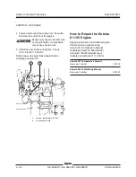
1 Connect the leads from an ohmmeter between
the far left glow plug and ground.
Result: The resistance should be approximately
1
Ω.
2 If the ohm reading is different than 1
Ω
, remove
the wire and connector plate from the three
individual glow plugs. Then, one glow plug at a
time, measure the resistance between the glow
plug and ground.
Result: The resistance should be approximately
1.8
Ω
for each individual glow plug.
3 Install the connector plate and wires to all three
glow plugs.
4 Turn the key switch to ground control and pull
out the red Emergency Stop button to the on
position.
5 Connect the red positive (+) lead from a volt
meter to the number three glow plug. Connect
the black negative (-) lead to ground.
6 Hold the glow plug switch in the on position.
Result: The volt meter should read 12V DC or
more.
Summary of Contents for GS-2669 RT
Page 169: ...Section 6 Schematics November2014 6 9 Control Panel Circuit Diagram 6 10 ...
Page 235: ...Section 6 Schematics November2014 6 75 6 76 Electrical Schematic GS 4069 RT Gas LPG Models AS ...
Page 238: ...November2014 Section 6 Schematics 6 78 Electrical Schematic GS 4069 RT Gas LPG Models AS 6 77 ...
Page 243: ...Section 6 Schematics November2014 6 83 Electrical Schematic GS 4069 RT Diesel Models AS 6 82 ...
Page 246: ...November2014 Section 6 Schematics 6 86 Electrical Schematic GS 4069 RT Diesel Models AS 6 85 ...
Page 251: ...Section 6 Schematics November2014 6 91 Electrical Schematic GS 4069 RT Gas LPG Models CE 6 92 ...
Page 254: ...November2014 Section 6 Schematics 6 94 Electrical Schematic GS 4069 RT Gas LPG Models CE 6 93 ...
Page 259: ...Section 6 Schematics November2014 6 99 6 100 Electrical Schematic GS 4069 RT Diesel Models CE ...
Page 267: ...Section 6 Schematics November2014 6 107 Hydraulic Schematic GS 2669 RT and GS 3369 RT 6 108 ...
Page 270: ...November2014 Section 6 Schematics 6 110 Hydraulic Schematic GS 4069 RT 6 109 ...


