Section 4 • Repair Procedures
November 2014
4 - 26
GS-2669 RT • GS-3369 RT • GS-4069 RT
Part No. 229753
KUBOTA D1105 ENGINE
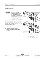
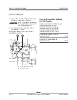
a
b
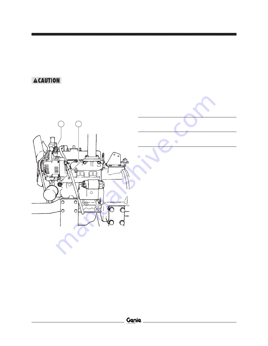
2 Tag and disconnect the wiring from the switch.
Remove the switch from the engine.
Bodily injury hazard. Contact with
hot engine fluids or components
may cause severe burns.
3 Install the new switch and tighten. Torque
to 8-18 ft-lbs / 11-24 Nm.
Note: Always use pipe thread sealant when
installing a new switch.
a
coolant temperature switch
b
oil pressure switch
How to Repair the Kubota
D1105 Engine
Repair procedures and additional engine
information are available in the
Kubota D1105 Operator's Manual
(Kubota part number 16622-89166).
Kubota D1105 Workshop Manual
(Kubota part number 9Y111-00123).
Kubota D1105 Operator's Manual
Genie part number
131379
Kubota D1105 Workshop Manual
Genie part number
229761
Summary of Contents for GS-2669 RT
Page 169: ...Section 6 Schematics November2014 6 9 Control Panel Circuit Diagram 6 10 ...
Page 235: ...Section 6 Schematics November2014 6 75 6 76 Electrical Schematic GS 4069 RT Gas LPG Models AS ...
Page 238: ...November2014 Section 6 Schematics 6 78 Electrical Schematic GS 4069 RT Gas LPG Models AS 6 77 ...
Page 243: ...Section 6 Schematics November2014 6 83 Electrical Schematic GS 4069 RT Diesel Models AS 6 82 ...
Page 246: ...November2014 Section 6 Schematics 6 86 Electrical Schematic GS 4069 RT Diesel Models AS 6 85 ...
Page 251: ...Section 6 Schematics November2014 6 91 Electrical Schematic GS 4069 RT Gas LPG Models CE 6 92 ...
Page 254: ...November2014 Section 6 Schematics 6 94 Electrical Schematic GS 4069 RT Gas LPG Models CE 6 93 ...
Page 259: ...Section 6 Schematics November2014 6 99 6 100 Electrical Schematic GS 4069 RT Diesel Models CE ...
Page 267: ...Section 6 Schematics November2014 6 107 Hydraulic Schematic GS 2669 RT and GS 3369 RT 6 108 ...
Page 270: ...November2014 Section 6 Schematics 6 110 Hydraulic Schematic GS 4069 RT 6 109 ...

