Section 4 • Repair Procedures
November 2014
4 - 28
GS-2669 RT • GS-3369 RT • GS-4069 RT
Part No. 229753
KUBOTA WG972 ENGINE
5-6
Engine RPM
How to Adjust the RPM
Note: The on-board self diagnostics incorporate a
built-in engine tachometer. The engine rpm is
displayed on the diagnostic display when the start
button is held to the start position with the engine
running.
Note: Perform this procedure in gasoline mode with
the engine at normal operating temperature.
1 Start the engine from the ground controls.
2 Hold the start button to the start position and
check the engine RPM on the diagnostic
display. Refer to Section 2,
Specifications
.
Proceed to step 9 if the low idle is correct.
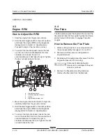
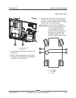
3 To correct the low idle speed, Loosen the core
clamp screw so the cable moves freely.
4 Loosen the lock nut on the high idle adjustment
nut.
5 Turn the high idle adjustment nut
counterclockwise until the adjustment nut is
flush against the solenoid.
6 Turn the lock nut against the adjustment nut. Do
not tighten.
7 Hold the throttle lever against the low idle
adjustment screw and turn the adjustment
screw clockwise to increase rpm or
counterclockwise to decrease rpm.
8 While holding the throttle lever against the low
idle adjustment screw, tighten the core clamp
screw.
9 Push the engine idle control button to high idle
(rabbit symbol) from the ground controls.
10 Hold the start button to the start position and
check the engine RPM on the diagnostic
display. Refer to Section 2,
Specifications
.
11 To correct the high idle speed, loosen the lock
nut on the high idle adjustment nut, turn the high
idle adjustment nut clockwise to increase the
rpm or counterclockwise to decrease the rpm.
Tighten the lock nut and confirm the rpm.
Note: Be sure the solenoid fully retracts when
activating high idle.
Summary of Contents for GS-2669 RT
Page 169: ...Section 6 Schematics November2014 6 9 Control Panel Circuit Diagram 6 10 ...
Page 235: ...Section 6 Schematics November2014 6 75 6 76 Electrical Schematic GS 4069 RT Gas LPG Models AS ...
Page 238: ...November2014 Section 6 Schematics 6 78 Electrical Schematic GS 4069 RT Gas LPG Models AS 6 77 ...
Page 243: ...Section 6 Schematics November2014 6 83 Electrical Schematic GS 4069 RT Diesel Models AS 6 82 ...
Page 246: ...November2014 Section 6 Schematics 6 86 Electrical Schematic GS 4069 RT Diesel Models AS 6 85 ...
Page 251: ...Section 6 Schematics November2014 6 91 Electrical Schematic GS 4069 RT Gas LPG Models CE 6 92 ...
Page 254: ...November2014 Section 6 Schematics 6 94 Electrical Schematic GS 4069 RT Gas LPG Models CE 6 93 ...
Page 259: ...Section 6 Schematics November2014 6 99 6 100 Electrical Schematic GS 4069 RT Diesel Models CE ...
Page 267: ...Section 6 Schematics November2014 6 107 Hydraulic Schematic GS 2669 RT and GS 3369 RT 6 108 ...
Page 270: ...November2014 Section 6 Schematics 6 110 Hydraulic Schematic GS 4069 RT 6 109 ...

