Section 4 • Repair Procedures
November 2014
Part No. 229753
GS-2669 RT • GS-3369 RT • GS-4069 RT
4 - 81
PLATFORM OVERLOAD COMPONENTS
14-2
Platform Overload Recovery
Message (software version B3
and later)
If the ground controls LCD screen displays
Ovrld
Recovery
, the emergency lowering system has
been used while the platform was overloaded.
Note: This message shall be cleared by a person
trained and qualified on the troubleshooting and
repair of this machine.
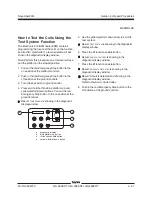
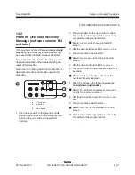
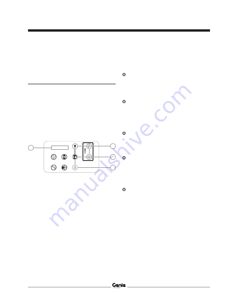
Note: Use the following illustration to identify the
description of each control button used in this
procedure.
b
c
d
a
a
LCD screen
b
up button
c
function enable button
d
down button
1 Turn the key switch to the ground controls
position and pull out the red Emergency stop
button to the on position at the platform
controls.
2 Press and hold both the up and down buttons.
Pull out the red Emergency Stop button to the
on position at the ground controls.
Result:
TUNE
SPEEDS
is showing in the LCD
screen.
3 Use the down button to scroll to
SELECT
OPTIONS
.
4 Press the function enable button.
Result:
DESCENT
DELAY
is showing in the LCD
screen.
5 Use the down button to scroll to
OVERLOAD
.
6 Press and hold the function enable button for 5
seconds.
Result: A screen will appear asking for the
overload recovery passcode.
7 Press the buttons in the following sequence:
(down) (down) (up) (enable)
.
Result: The LCD screen displays
CLEARED
and
returns to the
OVERLOAD
screen.
8 Use the down button to scroll to
RETURN
TO
MAIN
MENU
.
9 Press the function enable button.
Result:
SELECT
OPTIONS
is showing in the LCD
screen.
10 Push in the red Emergency Stop button to the
off position at the ground controls.
Summary of Contents for GS-2669 RT
Page 169: ...Section 6 Schematics November2014 6 9 Control Panel Circuit Diagram 6 10 ...
Page 235: ...Section 6 Schematics November2014 6 75 6 76 Electrical Schematic GS 4069 RT Gas LPG Models AS ...
Page 238: ...November2014 Section 6 Schematics 6 78 Electrical Schematic GS 4069 RT Gas LPG Models AS 6 77 ...
Page 243: ...Section 6 Schematics November2014 6 83 Electrical Schematic GS 4069 RT Diesel Models AS 6 82 ...
Page 246: ...November2014 Section 6 Schematics 6 86 Electrical Schematic GS 4069 RT Diesel Models AS 6 85 ...
Page 251: ...Section 6 Schematics November2014 6 91 Electrical Schematic GS 4069 RT Gas LPG Models CE 6 92 ...
Page 254: ...November2014 Section 6 Schematics 6 94 Electrical Schematic GS 4069 RT Gas LPG Models CE 6 93 ...
Page 259: ...Section 6 Schematics November2014 6 99 6 100 Electrical Schematic GS 4069 RT Diesel Models CE ...
Page 267: ...Section 6 Schematics November2014 6 107 Hydraulic Schematic GS 2669 RT and GS 3369 RT 6 108 ...
Page 270: ...November2014 Section 6 Schematics 6 110 Hydraulic Schematic GS 4069 RT 6 109 ...

