background image

Second Edition • Second Printing


Operator's Manual


Personal Safety 


Part No. 1278002GT


GS

-2669DC • GS

-3369DC • GS

-4069DC 


Pers onal Safety  

Personal Fall Protection 

Personal fall protection equipment (PFPE) is not 
required when operating this machine. If PFPE is 
required by job site or employer rules, the following 
shall apply: 

All PFPE must comply with applicable 
governmental regulations and must be inspected 
and used in accordance with the manufacturer’s 
instructions. 


Summary of Contents for GS-2669DC

Page 1: ...Operator s Manual GS 2669DC CE GS 3369DC GS 4069DC with Maintenance Information Original Instructions Second Edition Second Printing Part No 1278002GT...

Page 2: ...ety 10 Legend 18 Controls 19 Inspections 23 Operating Instructions 38 Transport and Lifting Instructions 49 Maintenance 52 Specifications 54 Copyright 2011 Terex Corporation Second Edition Second Prin...

Page 3: ...is Serial label location under chassis cover Intended Use This machine is intended to be used only to lift personnel along with their tools and materials to an aerial work site Bulletin Distribution a...

Page 4: ...hat applies to your machine Please register your machine by visiting us on the web at www genielift com or by calling us toll free at 1 800 536 1800 Danger Failure to obey the instructions and safety...

Page 5: ...tion Decals on this machine use symbols color coding and signal words to identify the following Safety alert symbol used to alert you to potential personal injury hazards Obey all safety messages that...

Page 6: ...rd Tip over hazard Tip over hazard Tip over hazard Electrocution hazard Electrocution hazard Explosion hazard Fire hazard Burn hazard Skin injection hazard Engage safety arm Keep away from moving part...

Page 7: ...C GS 3369DC GS 4069DC 5 Chock the wheels Release brakes Tiedown Lanyard anchorage points No smoking Wheel load Transport diagram Side force Wind speed Outrigger load Voltage rating for power to platfo...

Page 8: ...Operator s Manual Second Edition Second Printing General Safety 6 GS 2669DC GS 3369DC GS 4069DC Part No 1278002GT Gener al Safety...

Page 9: ...Second Edition Second Printing Operator s Manual General Safety Part No 1278002GT GS 2669DC GS 3369DC GS 4069DC 7...

Page 10: ...Operator s Manual Second Edition Second Printing General Safety 8 GS 2669DC GS 3369DC GS 4069DC Part No 1278002GT...

Page 11: ...Personal Fall Protection Personal fall protection equipment PFPE is not required when operating this machine If PFPE is required by job site or employer rules the following shall apply All PFPE must...

Page 12: ...nnel on the ground or in the platform must not touch or operate the machine until energized power lines are shut off Do not operate the machine during lightning or storms Do not use the machine as a g...

Page 13: ...it switches Do not drive over 0 48 km h with the platform raised Outdoor Use Do not raise the platform when wind speeds may exceed 12 5 m s If wind speeds exceed 12 5 m s when the platform is raised l...

Page 14: ...orm to adjacent structures Do not place loads outside the platform perimeter Do not push off or pull toward any object outside of the platform Maximum allowable manual force GS 2669DC Indoor use only...

Page 15: ...pacity battery option each battery must weigh 39 9 kg For GS 2669 and GS 3369 machines with the standard battery option each battery must weigh 28 1 kg Crushing Hazard Keep hands and limbs out of scis...

Page 16: ...the platform when raised Keep the platform floor clear of debris Do not enter or exit the platform unless the machine is in the stowed position Attach the platform entry chain or close the entry gate...

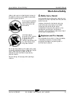
Page 17: ...ntrols of the crane have been locked out and or precautions have been taken to prevent any potential collision No stunt driving or horseplay while operating a machine Bodily Injury Hazard Do not opera...

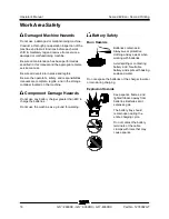
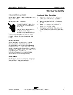
Page 18: ...are complete legible and in the storage container located on the machine Component Damage Hazards Do not use any battery charger greater than 48V to charge the batteries Do not use the machine as a g...

Page 19: ...inal equipment Batteries are used as counterweight and are critical to machine stability For GS 4069 machine each battery must weigh 39 9 kg For each GS 2669 and GS 3369 machine with high capacity bat...

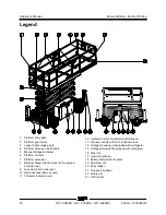
Page 20: ...n 8 Battery charger behind cover at the ground controls side 9 Ground controls side cover 10 Hydraulic tank behind cover 11 Tilt alarm behind cover 12 Hydraulic oil level indicator behind cover 13 Gro...

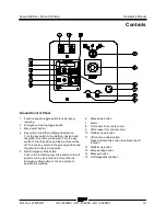
Page 21: ...off position and the machine will be off Turn the key switch to the ground position and the ground controls will operate 5 Red Emergency Stop button Push in the red Emergency Stop button to the off p...

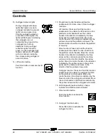
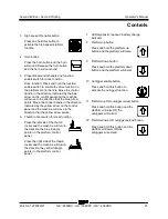
Page 22: ...atform Control Panel 1 Low speed lift enable button Press and hold this button to activate the low speed platform function 2 Red Emergency Stop button Push in the red Emergency Stop button to the off...

Page 23: ...l and the machine will move in the direction that the yellow arrow points 6 Thumb rocker switch for steer function Press the left side of the thumb rocker and the machine will turn in the direction th...

Page 24: ...latform will raise Move the control handle in the direction indicated by the yellow arrow and the platform will lower The descent alarm should sound while the platform is lowering Drive function Press...

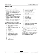
Page 25: ...e inspection is designed to discover if anything is apparently wrong with a machine before the operator performs the function tests The pre operation inspection also serves to determine if routine mai...

Page 26: ...ttings cylinders and manifolds Drive motors Wear pads Tires and wheels Limit switches alarms and horn Alarms and beacons if equipped Nuts bolts and other fasteners Brake release components Safety arm...

Page 27: ...e 5 Only use the machine as it was intended Function Test Fundamentals The function tests are designed to discover any malfunctions before the machine is put into service The operator must follow the...

Page 28: ...Pull out the red Emergency Stop button to the on position Test the Up Down Functions The audible warnings on this machine and the standard horn all come from the same central alarm The horn is a cons...

Page 29: ...ton to the on position 23 Press the horn button Result The horn should sound Use the button pattern on the platform controls to determine which of these next two function tests to perform Use this fun...

Page 30: ...tton or the platform down button Result The platform should stop lowering Use this function test procedure if the decal on your platform controls has these buttons Test the Function Enable Switch and...

Page 31: ...the thumb rocker switch on top of the control handle in the direction indicated by the yellow triangle on the control panel Result The steer wheels should turn in the direction indicated by the yellow...

Page 32: ...e drive function button if equipped 66 Press and hold the function enable switch on the control handle 67 Move the control handle in the direction indicated by the blue arrow then move the control han...

Page 33: ...not exceed 1 34 m per second If the drive speed in reverse with the platform stowed exceeds 1 34 m per second immediately tag and remove the machine from service Use the button pattern on the platfor...

Page 34: ...direction indicated by the yellow arrow Result The machine should not move in the directions indicated by the blue and yellow arrows 86 Press and hold the function enable switch on the control handle...

Page 35: ...trigger indicator lights turn solid green and a long beep is heard from the platform controls alarm The machine is now level At this point the drive and steer functions are disabled Note If the contro...

Page 36: ...o time out 108Slowly move the control handle in the direction indicated by the blue arrow then in the direction indicated by the yellow arrow Result The outriggers should not retract 109Press the outr...

Page 37: ...ps the operator determine if the workplace is suitable for safe machine operation It should be performed by the operator prior to moving the machine to the workplace It is the operator s responsibilit...

Page 38: ...it Switch 1 114338 Label Tip over Hazard Tilt Alarm 1 114371 Label Outrigger Safety 1 137605 Label Emergency Stop Platform Control 1 137656 Label Drive Steer Direction Platform Control 1 Part No Decal...

Page 39: ...Second Edition Second Printing Operator s Manual Inspections Part No 1278002GT GS 2669DC GS 3369DC GS 4069DC 37...

Page 40: ...tion It is the operator s responsibility to follow all the safety rules and instructions in the operator s safety and responsibilities manuals Using the machine for anything other than lifting personn...

Page 41: ...to ground control 3 Pull out both ground and platform red Emergency Stop buttons to the on position To Position Platform 1 At the control panel press and hold the lift function enable button 2 Press t...

Page 42: ...ndicator lights will turn off as the corresponding outrigger retracts Machine functions are restored once the outrigger are off the ground Note Drive function is disabled while the outriggers are down...

Page 43: ...ction enable switch on the control handle 3 Move the control handle in the direction indicated by the yellow arrow The outriggers will begin to extend The individual outrigger indicator light will tur...

Page 44: ...nction symbol will turn off and drive function will not operate Press the drive function button again 2 Turn the steer wheels with the thumb rocker switch located on the top of the control handle To D...

Page 45: ...slope with a digital inclinometer OR use the following procedure You will need carpenter s level straight piece of wood at least 1 m long tape measure Lay the piece of wood on the slope At the downhi...

Page 46: ...orm was overloaded For information on how to reset this message please consult the appropriate Genie Service Manual Operational indicator codes If the platform controls LED or ground controls LCD diag...

Page 47: ...to cool for approximately 5 minutes before resuming machine operation 3 Pull out the red Emergency Stop button to the on position Operation from Ground with Controller Maintain safe distances between...

Page 48: ...platform To Extend and Retract Platform 1 Lift the platform extension lock handles to the horizontal position 2 Push the platform extension lock handles to extend the platform to the desired position...

Page 49: ...ment The compartment should remain open for the entire charging cycle Maintenance free batteries 1 Connect the battery charger to a grounded AC circuit 2 The charger will indicate when the battery is...

Page 50: ...h cell with battery acid electrolyte until the level is sufficient to cover the plates Do not fill to maximum level until the battery charge cycle is complete Overfilling can cause the battery acid to...

Page 51: ...o prevent rolling while the machine is being loaded Be sure the vehicle capacity loading surfaces and chains or straps are sufficient to withstand the machine weight Genie lifts are very heavy relativ...

Page 52: ...transport Retract and secure the extension deck Use the tie down points on the chassis for anchoring down to the transport surface Use a minimum of 2 chains or straps Use chains or straps of ample loa...

Page 53: ...nsion deck controls and component trays are secure Remove all loose items on the machine Determine the center of gravity of your machine using the table and the picture on this page Attach the rigging...

Page 54: ...one or more of the symbols appear at the beginning of a maintenance procedure it conveys the meaning below Indicates that tools will be required to perform this procedure Indicates that new parts wil...

Page 55: ...ing soda and water Note Perform this test after fully charging the batteries 1 Put on protective clothing and eye wear 2 Be sure that the battery cable connections are tight and free of corrosion 3 Be...

Page 56: ...um hydraulic pressure functions 241 bar Tire size 26 x 12 x 380 Airborne noise emissions Sound pressure level at ground workstation 70 dBA Sound pressure level at platform workstation 70 dBA Total vib...

Page 57: ...aulic pressure functions 241 bar Tire size 26 x 12 x 380 Airborne noise emissions Sound pressure level at ground workstation 70 dBA Sound pressure level at platform workstation 70 dBA Total vibration...

Page 58: ...e emissions Sound pressure level at ground workstation 70 dBA Sound pressure level at platform workstation 70 dBA Total vibration value to which the hand arm system is subjected does not exceed 2 5 m...

Page 59: ......
Reviews: