August 2018
Part No. 57.4400.9220GT
GTH-2506 GTH-3007
4-39
Section 4 • Repair Procedures
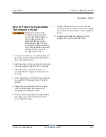
8-1
LMI
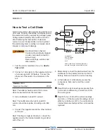
How to Remove a Load Cell
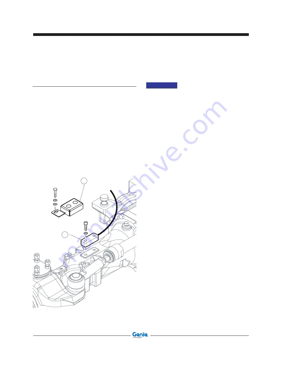
1 Go to the back of the machine. The load cell "b"
is installed on the axle near the right wheel.
2 Remove the retaining fasteners that secure
guard "a". Remove the guard.
3 Disconnect the harness from the load cell.
4 Remove the retaining fasteners that secure the
load cell. Remove the load cell.
How to Install the Load Cell
NOTICE
The extensometer and the axle
must be stored at a similar
temperature before the mounting
operation. The time is linked
to the thermal inertia of both
pieces (extensometer: 1 hour for
ΔT
=20°C).
1 The extensometer must be mounted without
any strain on the axle.
2 Place the extensometer with the 2 screws M10
(should be easy to tight the screws by hands):
to improve the tightening force applied by
the screws and to prevent any loosening, we
recommend to use Loctite 242.
3 The tightening operation of the 2 M10 screws
should be done progressively:
- Tightening of screw n.1 at torque T1=40 Nm
- Tightening of screw n.2 at torque T1=40 Nm
- Tightening of screw n.1 then screw n.2 at
torque T2=65 Nm.
4 Nominal torque : T= 65 Nm ± 5% for M10
screws quality 12.9 with lubrication due to the
LOCTITE glue before polymerisation (μ=0,15
and F ~ 3500 daN).
Time of polymerization of the glue: 1 hour at
ambient temperature before using.
Instructions before calibration procedure
1 Make a mechanical running in (preloading the
axle) before calibration of the extensometer
with the display.
2 This mechanical running in consists in making
the axle work to a level of strain equivalent to 3
times the nominal level of strain in the axle for
the full range in static.
LMI (Overload System)
a
b


