background image

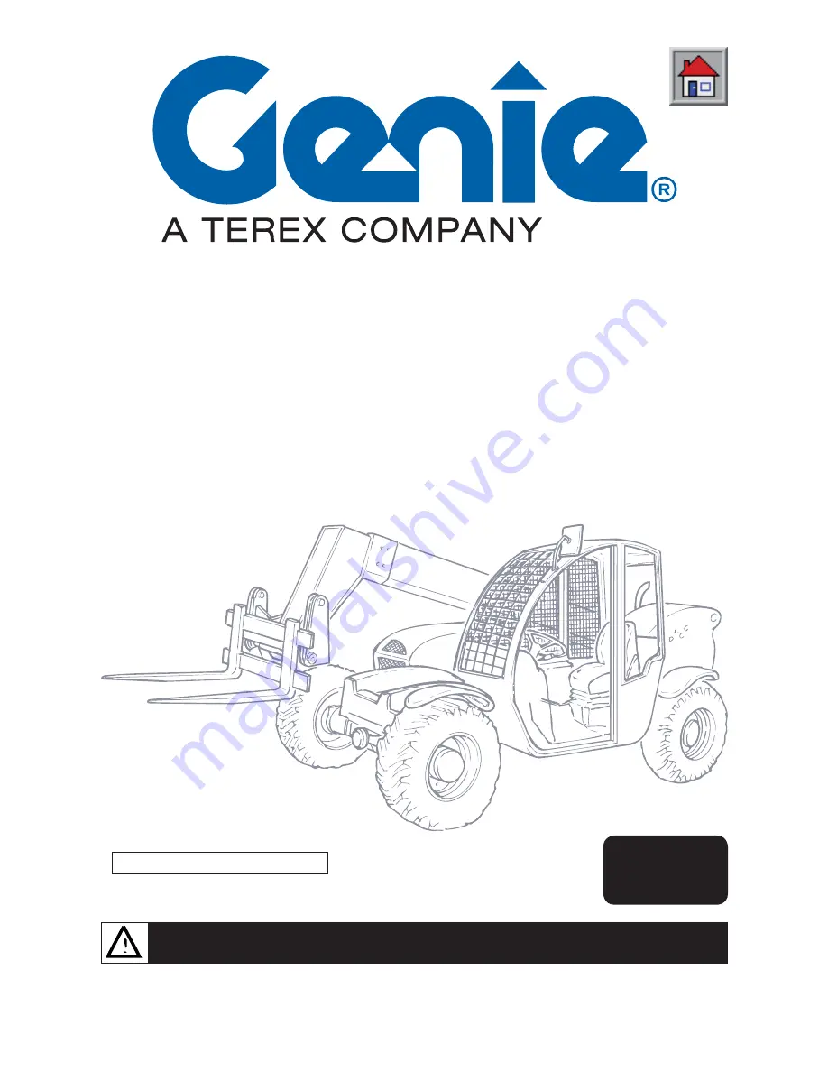
Handler with telescopic boom

GTH-6622

OPERATOR HANDBOOK

Code 57.0005.8200 - Rev.0 12/2005

CAUTION: THOROUGHLY READ AND UNDERSTAND THIS HANDBOOK BEFORE OPERATING THE MACHINE

CAUTION: KEEP THIS HANDBOOK IN THE MACHINE AT ALL TIMES

English 

Edition

Before Serial Number: 18723

Summary of Contents for GTH-6622

Page 1: ...622 OPERATOR HANDBOOK Code 57 0005 8200 Rev 0 12 2005 CAUTION THOROUGHLY READ AND UNDERSTAND THIS HANDBOOK BEFORE OPERATING THE MACHINE CAUTION KEEP THIS HANDBOOK IN THE MACHINE AT ALL TIMES English E...

Page 2: ...oduced by Genie Scandinavia Phone 46 31 575100 Fax 46 31 579020 Genie France Phone 33 0 2 37 26 09 99 Fax 33 0 2 37 26 09 98 Genie Iberica Phone 34 93 579 5042 Fax 34 93 579 5059 Genie Germany Phone 4...

Page 3: ...LIST OF REVISED PAGES Revision Revised Issued No date pages Notes by 1 2 3 4 5 6 7 8 9 10 11 12 13 14 15 16 17 18 19 20 21 22 23 24 25 26 27 28 29 30 31 32 33 34 35 36 37 38 39 40...

Page 4: ...LIST OF REVISED PAGES Revision Revised Issued No date pages Notes by 1 2 3 4 5 6 7 8 9 10 11 12 13 14 15 16 17 18 19 20 21 22 23 24 25 26 27 28 29 30 31 32 33 34 35 36 37 38 39 40...

Page 5: ...machine parking machine storing Section D is addressed to the maintenance responsible and the servicemen The section describes the maintenance schedule and the relevant intervals Section E deals with...

Page 6: ...ss of the hazard situation DANGER Draws the attention to situations that involve your own as well as the others safety and that can result in serious or lethal injury ELECTRICAL DANGER Draws the atten...

Page 7: ...dler with telescopic boom GTH 6622 GENERAL INDEX GENERAL INFORMATION Sect A SAFETY Sect B OPERATING INSTRUCTIONS Sect C MAINTENANCE Sect D TROUBLESHOOTING Sect E OPTIONAL ATTACHMENTS Sect F TABLES AND...

Page 8: ...Document 57 0005 8200 12 2005 Page 4 Handler with telescopic boom GTH 6622 Intentionally blank page...

Page 9: ...plates of the main parts A 9 A 3 ALLOWED USE A 10 A 3 1 Allowed use A 10 A 3 2 Improper use A 10 A 3 3 Residual hazards A 10 A 3 4 Applicable standards A 11 A 3 5 Safety devices A 12 A 4 GENERAL DESCR...

Page 10: ...POSITION Conventionally the machine should be considered positioned as shown in the figure This convention is necessary to make any reference of this handbook to different machine parts front rear etc...

Page 11: ...those that become unreadable either graphic or text To clean labels use of a soft cloth water and soap Never use solvents petrol etc When a label is applied on a part to be replaced make sure that th...

Page 12: ...1 09 4618 0010 97671 97667 97675 97664 09 4618 0109 09 4618 0642 09 4618 0547 97664 82558 09 4618 0547 97688 97664 97674 topofchassis 97664 boomrest 97668 97665 97672 97666 97669 0 20 40 6 0 80 P 5 5...

Page 13: ...of crushing 97673 Prohibition to lift people 97674 Risk of crushing 97675 Risk of explosion burns 97676 Electrical hazard 97688 Emergency exit handle 09 4616 0051 Hydraulic oil 09 4616 0101 Machine d...

Page 14: ...now part of the common life But we consider useful to explain them once again Symbol Description IMPORTANT Spend the necessary time to become familiar with these symbols and to learn their meaning Haz...

Page 15: ...A 7 GENERAL INFORMATION Front optional work light Lifting point Fuel plug Engine oil filler Continuous flow selector Pushbutton enabling the attachment coupling release Horn pushbutton Mechanical gea...

Page 16: ...triale Ind Estate I 06019 UMBERTIDE PG ITALY Enrolled in the register of companies at the Court of Perugia under no 4823 C C I A A n 102886 Fiscal Code V A T no 00249210543 A 2 3 MACHINE IDENTIFICATIO...

Page 17: ...SERIAL NUMBER The chassis serial number is punched on the front left part of the chassis side member A 2 5 IDENTIFICATION PLATES OF THE MAIN PARTS The plates of the main components not directly manuf...

Page 18: ...tructions of this manual and that in general may result in risks for both operators and bystanders DANGER We list below some of the most frequent and hazardous situations of improper use Carrying pass...

Page 19: ...l characteristics and testing ISO DIS 3287 Poweredindustrialtrucks Pictorialsigns Control symbols ISO 3449 1992 Earth movingmachinery Falling object protective structures Laboratory tests and performa...

Page 20: ...the front axle which engages automatically when the engine stops When this brake is disengaged the engine start up is inhibited Block valves fitted to all cylinders A Block valve on attachment coupli...

Page 21: ...GENERAL DESCRIPTION A 4 1 LIST OF THE MAIN COMPONENTS 1 Forks 2 Attachment holding frame 3 2nd boom section 4 1st boom section 5 Engine hood 6 Driving cab 7 Left rear view mirror 8 Front axle 9 Chass...

Page 22: ...capacity Boom hydraulic circuit It consists of a gear pump connected to the thermal engine which through a special valve dispenses oil to the hydraulic drive and a distributor for the following functi...

Page 23: ...heel base ft 8 8 F Length to the front tyres ft 13 5 G Length to the attachment holding plate ft 15 5 H Ground clearance ft 1 4 Internal steering radius ft 7 2 External steering radius ft 13 3 A 5 2 R...

Page 24: ...line 4 strokes direct injection Bore x Stroke in 3 7 x 4 41 Total displacement cu in 189 65 Power at 2500 rpm ISO 3046 IFN kW 60 A 5 8 ELECTRICAL SYSTEM Voltage V 12 Battery Ah 100 A 5 9 MACHINE SOUN...

Page 25: ...t compulsorily be inspected and tested by the Manufacturer before being used again A 7 ITEMS SUPPLIED Following items are supplied together with the machine Description GTH 6622 Spanner CH 19 for fork...

Page 26: ...Document 57 0005 8200 12 2005 Handler with telescopic boom GTH 6622 Page A 18 GENERAL INFORMATION Intentionally blank page...

Page 27: ...2 B 2 PREREQUISITES OF THE PERSONNEL IN CHARGE B 2 B 2 1 Requisites of the machine operators B 2 B 2 2 Requisites of the servicemen B 3 B 2 3 Working clothes B 3 B 2 4 Personal protective equipment B...

Page 28: ...better to ask For this purpose contact GENIE the assistance service is atyourdisposal Addresses phoneandfaxnumbers are given in the cover and in the title page of this manual B 2 REQUISITES OF THE PER...

Page 29: ...n and warning plates They shall be skilled and trained about the machine functioning IMPORTANT From a technical point of view the ordinary maintenance of the machine is not a complex intervention and...

Page 30: ...ould hinder the machine movements and represent a danger for personnel DANGER DEATH OR INJURY CAN RESULT FROM CONTACTING ELECTRIC POWER LINES ALWAYS CONTACT THE ELECTRIC POWER LINES OWNER THE ELECTRIC...

Page 31: ...ays pay the greatest attention Do not walk or stop under raised loads or machine parts supported by hydraulic cylinders or ropes only Keep the machine handholds and access steps always clean from oil...

Page 32: ...ose Absolutely avoid to use tools in bad conditions or in an improper way i e pliers instead of adjustable wrenches etc Before carrying out operations on hydraulic lines under pressure or disconnectin...

Page 33: ...ing do not give instructions or signs to several people at the same time Instructions and signs must be given by one person only Always pay the due attention to the instructions given by the foreman N...

Page 34: ...Document 57 0005 8200 12 2005 Handler with telescopic boom GTH 6622 Page B 8 SAFETY Intentionally blank page...

Page 35: ...Light indicators C 13 C 3 4 Control lever C 14 C 3 4 1 Function selection C 15 C 3 4 2 Lifting lowering the boom C 16 C 3 4 3 Pitching the attachment holding frame forward back C 17 C 3 4 4 Extending...

Page 36: ...s safety and the machine integrity It is necessary to learn how to use and foresee the machine reactions Learn how to operate the machine controls in a safe and open place without obstacles and anybod...

Page 37: ...nd side Door opening from outside Insert the key and release lock 1 Press the pushbutton and open the door Door closing from inside Pull the door with force it locks automatically Door opening from in...

Page 38: ...R GLASS KIT INSTALLED In an emergency the operator can use he front or the rear window as safety exit ways The rear window has handles for partially opening the glass Such handles are locked in positi...

Page 39: ...ed Rotate clockwise anticlockwise to increase reduce the seat springing To reverse this control pull out and rotate the lever knob by 180 Height adjustment optional Turn knob 3 clockwise to lift the s...

Page 40: ...windscreen and allows checking the area behind the machine on the left hand side To adjust its position manually rotate the joint it is fitted with C 2 4 ADJUSTING THE STEERING COLUMN Both steering co...

Page 41: ...dler with telescopic boom GTH 6622 Page C 7 OPERATING INSTRUCTIONS C 3 DRIVING PLACE 40 80 120 C 0 1 2 3 4 5 6 7 80 120 C 40 10 8 6 0 4 2 2 4 6 8 10 12 2 13 14 15 17 8 24 7 F R N 16 3 23 18 19 20 21 2...

Page 42: ...ng selection switch 15 Horn pushbutton 16 Mechanical gear selector 17 Gas pedal 18 Fresh air flap 19 Control lever 20 Continuous flow selector 21 Negative brake on off switch 22 Storage tray 23 Seat 2...

Page 43: ...der voltage presetting for the engine starting Board controls and instruments are on The warning light 6 signalling the glow plugs preheating comes on Wait until the light goes off before starting the...

Page 44: ...ted pressing the pushbutton switch 21 unlocks the parking brake To stop the handler without shutting down the engine press the pushbutton switch 21 to engage the parking brake and push it once again t...

Page 45: ...selector 20 Selection button Button with two stable positions 1 Pressing this selector delivers a continuous flow of oil to the attachment in use The built in light switches on 2 Pressing this selecto...

Page 46: ...Three position switch 0 OFF 1 Low speed 2 High speed 27 Cab heater control cock only with cabin closed To the right of the driving seat Turn the heated air regulator 27 counter clockwise so the air h...

Page 47: ...ator light air filter soiled Not activated 64 Indicator light low battery charge Signals a low charge by the alternator 65 Indicator light low engine oil pressure It lights when the engine oil pressur...

Page 48: ...directions right left forwards backwards moves the boom up and down and the telescope out and in IMPORTANT Seize the control lever correctly and move it gently The motion speed of the actuators depen...

Page 49: ...enabled to carry out the following motions Boom lowering lifting shift the control lever to or Boom extraction retraction shift the control lever to or Attachment back forward tilting press button and...

Page 50: ...ge C 16 OPERATING INSTRUCTIONS C 3 4 2 Lifting lowering the boom CAUTION Before operating the boom make sure that nobody is within the working range of the machine To lift or lower the boom Smoothly s...

Page 51: ...he attachment holding frame forwards backwards CAUTION Before operating the boom make sure that nobody is within the working range of the machine To tilt the attachment holding frame forwards backward...

Page 52: ...ING INSTRUCTIONS C 3 4 4 Extending retracting the telescope CAUTION Before operating the boom make sure that nobody is within the working range of the machine To extend or retract the boom telescope S...

Page 53: ...ing the attachments CAUTION Before operating the boom make sure that nobody is within the working range of the machine To lock the attachments Press button together with the button on the dashboard to...

Page 54: ...he machine start up Check the efficiency of the safety devices as described in chap D 3 15 namely machine start control C 4 2 STARTING THE ENGINE For the low temperature starting see paragraph C 4 4 P...

Page 55: ...the special control levers Put the gear lever to neutral and engage the parking brake Ensure the machine battery A is connected to the frame earth the terminals are well tightened and the electrolyte...

Page 56: ...ncaseofenginejump starting removethebooster ables see chapter C 4 3 C 4 5 DISCONNECTING THE BATTERY Before any maintenance or repair work and especially before welding any components on the machine re...

Page 57: ...hold to the handholds to prevent falls or slips DANGER Always engage the parking brake after stopping themachinetopreventpossibleaccidentalmotions of the vehicle C 5 USING THE HANDLER This chapter des...

Page 58: ...afe conditions always refer to these charts CAUTION Theloadchartsillustratedinthismanualaregivenonly as a mere example To define the payload limits refer to the load charts applied in the cab of your...

Page 59: ...rks and slide them on the pivot until correct spacing Lock the screws re tightening the nut CAUTION The centre of gravity of the load must always be halfway between the forks Ensure you exactly know t...

Page 60: ...tart or brake abruptly Drive to the unloading point cautiously and keep the load 20 30 cm from the ground Suit the machine speed to the ground conditions to avoid dangerous jumps side skids of the veh...

Page 61: ...king pipes of the attachments to couplings A Rest the attachment flat on the ground Pitch the attachment holding frame forward and lower the boom to release the attachment upper lock Move back with th...

Page 62: ...ke see chap C 6 1 1 Tow the machine for short distances and at a low speed only Use a rigid drawbar Select the two wheel steer Set the gearbox lever to neutral When possible start the engine and use t...

Page 63: ...ke sure the instruments are in efficient working order Start the machine Select the forward or reverse speed The transfer speed of the vehicle will depend on the engine rpm CAUTION Public road circula...

Page 64: ...e ramps are correctly positioned Retract the boom to transfer position Carefully drive the machine onto the transporting vehicle Put the parking brake and rest the attachment flat on the vehicle platf...

Page 65: ...etter cleaning remove grills and protection casings Carefully dry all machine parts by blowing some compressed air Lubricate the machine thoroughly Do a walk around inspection and replace any worn or...

Page 66: ...ACHINE DISPOSAL PROTECT THE ENVIRONMENT At the end of the machine life call in a specialised firm to dispose of it in compliance with the local or national regulations C 6 7 1 Battery disposal PROTECT...

Page 67: ...filter canisters on the intake line D 13 D 3 10 1 Transmission oil filter D 13 D 3 10 2 Auxiliary circuits oil filter D 14 D 3 11 Oil level in the differential gears and the rducer D 15 D 3 11 1 Fron...

Page 68: ...efer to the specific Operator handbook supplied with the machine D 1 LUBRICANTS HEALTH AND SAFETY PRECAUTIONS Health A prolonged skin contact with oil can cause irritation Use rubber gloves and protec...

Page 69: ...ine 8 Check the efficiency of the lighting electric system 9 Checktheefficiencyofbrakingsystemandparking brake 10 Check the efficiency of the steering selection system 11 Check the efficiency of the f...

Page 70: ...ilter 9 Clean or replace if nececessary the air filter in the cab Every 1000 working hours or yearly Jobs to be done in addition to those above 1 Changetheoilinthefrontandreardifferentialunits and in...

Page 71: ...ure there is no residual pressure Forthispurpose stoptheengine engage the parking brake and operate the control levers of the distributors in both working directions alternately to depressurise the hy...

Page 72: ...tion cup Battery To get access to the engine compartment Shut the engine down and put the parking brake Unlock the bonnet lock Lift the bonnet using the special handle until it latches in the gas spri...

Page 73: ...reaser from the telescopes before smearing them with new grease Regularly grease the machine to grant it efficient conditions and a long life By means of a pump inject grease into the special greasers...

Page 74: ...placed check the nut torque of the wheels every 2 hours until they stay correct ATTENTION Always use tyres having the dimensions indicated in the vehicle registration card For the tyre inflation or su...

Page 75: ...king brake circuit To bleed the circuit of the service brake Make sure that the oil is level within the feeding tank Step on the brake pedal repeatedly Slowly unscrew valve and re close it as soon as...

Page 76: ...hten wingnut C close cover B and tighten with wingnut A ATTENTION As soon as the warning lamp 7 on the cab dashboard switches on replace the outer element 2 Changing the internal element See step 1 fo...

Page 77: ...cloth is damged 1 Cleaning and changing the cartridge Shut the engine down and engage the parking brake Pull out the filter A located to the left of the driving place Clean the filter bowl Clean the f...

Page 78: ...rom the hydraulic circuit 3 Place a container of suitable size under the drain plug placed in the lower part of the reservoir and collect any oil leaks 4 Remove the drain plug and allow oil to flow ou...

Page 79: ...hydraulic oil filter element on the suction line proceed as follows 1 Stop the machine on a level ground and engage the parking brake 2 Place a container of suitable size under the filter to collect...

Page 80: ...llows 1 Stop the machine on a level ground and engage the parking brake 2 Remove the inspection hatch and unscrew the oil filter fitted inside the tank 3 Check the tank is clean then fit a new filteri...

Page 81: ...plug Add new oil through plug until it is level with the hole Refit and tighten level filler plug D 3 11 2 Reducer To check the oil level in the reducer Stop the machine on a level ground and engage...

Page 82: ...he oil change Stop the machine and ensure the plug is oriented along the vertical axis Placeacontainerofsuitablesizeunderthereduction gear plug Unscrewplug anddrainanyoilfromthereduction gear Rotate t...

Page 83: ...low 1 Move to a solid and level ground 2 Setthesteeringselectionswitch14to four wheel steer pos 2 3 Rotate the steering up to its stop either to the right or to the left 4 Set the steering selection s...

Page 84: ...shims If the residual thickness of the pad is insufficient or near the maximum wearing limit renew the pad Tighten the screws fixing the pads at the recommended torque see below Use a dynamometric wr...

Page 85: ...to the cylinder of which you are checking the valve with caution During the check the oil will flow out of the hoses and the load shall remain blocked in position Should that not be the case the valv...

Page 86: ...D 20 MAINTENANCE Checking the machine start control at every use Attempt to start the engine with the forward or reverse gear put The engine must not start If the engine starts contact the GENIE Tech...

Page 87: ...es your skin and eyes Always wear goggles and protective gloves and handle the battery with caution to prevent spillage Keep metal objects watch straps rings necklaces clear of the battery leads since...

Page 88: ...l 15 F4 Front right rear left position lights license plate lights position lights indicator engine oil temperature indicator 5 F5 Front left rear right position lights fuel gauge hourmeter warning la...

Page 89: ...ef Circuit Amp F30 Preheating control unit maxifuse 70 F31 System protection fuse 50 A02 Preheating control unit K11 Start relay K1 K2 K3 K4 K6 K5 F1 F2 F3 F4 F5 F6 F7 F8 F9 F10 F11 F12 F13 F14 F15 F1...

Page 90: ...21 5 W Beacon Work lights OPTIONAL 12 V H3 55 W Dashboard indicators and cab lighting 12 V W 2x4 6d 1 2 W Interior lamp 12 V SV 8 5 8 5 W License plate lights 12 V BA 15s 5 W Back up lamps 12 V BA 15s...

Page 91: ...ATIONS D 5 2 1 Engine oil Use the oil recommended by the Diesel engine Manufacturer see the relevant handbook delivered with the machine At the delivery the machine is refilled with SHELL RIMULA 15W 4...

Page 92: ...Diesel fuel or oil diesel fuel or oil diesel fuel mixtures The composition of the latter can vary in relation to the ambient temperature up to max 80 oil D 5 2 4 Grease For the machine greasing use A...

Page 93: ...0005 8200 12 2005 Handler with telescopic boom GTH 6622 Page E 1 FAULTS AND TROUBLESHOOTING E 1 FAULTS AND TROUBLESHOOTING E 2 E 1 1 Fault Cause Solution E 2 Section E FAULTS AND TROUBLESHOOTING TABLE...

Page 94: ...VEN WHEN SELECTING THE JOBSITE FUNCTION The 50A fuse F31 supplying power to the dashboard is blown engine compartment Battery disconnected Battery down Battery cut out switch OFF Speed selector switch...

Page 95: ...ormal when the outside tem perature is low and or the machine is used for short periods since the hydraulic oil cannot warm up over 40 50 C Fuse blown Fuse blown ROAD JOBSITE switch set to ROAD Emerge...

Page 96: ...Document 57 0005 8200 12 2005 Handler with telescopic boom GTH 6622 Page E 4 FAULTS AND TROUBLESHOOTING NOTES...

Page 97: ...telescopic boom GTH 6622 Page F 1 OPTIONAL ATTACHMENTS F 1 1 Shovel F 3 F 1 2 Cereal shovel F 4 F 1 3 Fixed hook on plate F 5 F 1 4 Extension jib F 6 F 1 5 Forks with hydraulic side shift F 7 Section...

Page 98: ...and especially the extension jib can change the centre of gravity of the machine Before handling a load check its weight and compare it with the values on the load charts The weight of the used attac...

Page 99: ...sand debris cereals etc Safety Strictly obey the general safety precautions given in section B SAFETY Operation ATTENTION When using a shovel load the material only when the boom is completely retrac...

Page 100: ...tion B SAFETY Operation ATTENTION When using a shovel load the material only when the boom is completely retracted and push against the heap with straight wheels To load unload the material operate th...

Page 101: ...ns of the locking cylinder All loads must be bridled with special textile slings or chains in compliance with all pertinent regulations To handle the load raise and rotate the telescopic boom of the h...

Page 102: ...ck coupling fitted attachment for maintenance interventions at high working heights Safety Strictly obey the general safety precautions given in section B SAFETY Never lift wrongly slung loads Avoid a...

Page 103: ...shifting the load to the side by 100 mm Safety Strictly obey the general safety precautions given in section B SAFETY Do not load loose materials Do not move superposed pallets Operation To adjust the...

Page 104: ...Document 57 0005 8200 12 2005 Handler with telescopic boom GTH 6622 Page F 8 OPTIONAL ATTACHMENTS Intentionally blank page...

Page 105: ...Load Chart with forks G 3 G 3 1 Wiring diagram Fuses and relays G 4 G 3 1 1 Fuse and relay box G 5 G 3 2 Wiring diagram G 7 G 3 2 1 Wiring diagram Components description G 15 G 3 3 Wiring diagram Conn...

Page 106: ...90 228 M 14 x 1 5 28000 56000 78800 94500 71 7 143 202 242 M 16 x 2 35200 70300 98900 119000 102 205 288 346 M 16 x 1 5 37400 74800 105000 126000 107 214 302 362 M 18 x 2 5 43000 86000 121000 145000 1...

Page 107: ...ABLES AND DOCUMENTS ENCLOSED G 2 1 LOAD CHART WITH FORKS GTH 6622 15 0 0 5 10 15 6 6 0 0 l b 5 5 0 0 l b 3000 lb 4 4 0 0 l b 3 A B C D E A D E Forward reach ft ft GTH 6622 CAPACITY CHART 3300 lb 20 25...

Page 108: ...reheating control unit power supply 5 F16 Not used 15 F17 Not used 15 F18 Not used 15 F19 Not used 7 5 F20 Not used 10 F21 Not used 10 F22 Not used 10 F23 Not used 7 5 F24 Not used 5 F25 Not used 10 F...

Page 109: ...7 5A 25A 28 10A 10A 26 27 14 11 12 13 3 6 2 1 5 4 10A 5A 24 25 7 5A 10A 23 87 E5 85 86 87 E4 87A 30 10A 21 15A 19 20 7 5A 87A E3 86 85 87A 30 85 86 87 30 22 87 E10 85 86 87 E9 87A 30 87A E8 86 85 87A...

Page 110: ...Document 57 0005 8200 12 2005 Handler with telescopic boom GTH 6622 Page G 6 TABLES AND DOCUMENTS ENCLOSED Intentionally blank page...

Page 111: ...BK 1 5 3 BN 2 5 F13 PK 1 5 5A X3 2 C7 PK 1 5 SW03 BN 2 5 X5 OG GN 1 5 2 C7 1 2 X3 BN BK 1 5 BU RD 1 RD 6 BK 50 WH RD 1 5 24 X2 VT WH 1 5 P WH RD 1 BN 4 4 E8 BU RD 1 BK 1 SS09 6 X2 GY BU 1 GY BU 1 X3 1...

Page 112: ...X2 BK 1 OG BK 1 X2 13 OG BK 1 GN RD 1 30 PK 1 5 86 BN BK 1 5 85 87 87A HA01 Y02 4 B8 RD 1 87A 87 85 RD 1 86 TQ RD 1 30 K04 BK 1 GN RD 1 SOLENOID VALVE FORWARD SPEED FORWARD SPEED RELAY X2 5 LIST OF A...

Page 113: ...HA02 BK 1 VT 1 M03 SW05 REAR 31 4 A10 4 G10 4 G10 30 15 2 G10 2 G10 30 15 31 2 A1 WIPER WASHER HORN SWITCH HORN WIND SCREEN WIND SCREEN WIPER WASHER FRONT MOTOR SWITCH WIPER WASHER WIND SCREEN LIST O...

Page 114: ...RD 1 BU RD 1 WH GN 1 BK 1 YE 1 J7 J8 J9 J3 J2 J6 J5 WH BU 1 GY WH 1 GY YE 1 RD BK 1 J12 J1 J4 J11 J10 J13 J15 J14 31 15 30 3 G10 3 G10 15 30 5 G10 5 G10 5 A10 31 LIGHT DASHBOARD INDICATOR FUEL FLOAT...

Page 115: ...ENT SOLENOID VALVE 12v 2 1 BK 1 Y10 OG YE 1 X2 12 OG YE 1 X5 6 OG YE 1 WH YE 1 5 X5 WH YE 1 RD 1 RD 1 BK 1 SW04 RD BK 1 4B8 RD BK 1 3 6 0 7 1 4 2 5 8 1 6 A10 6 G10 6 G10 30 15 31 30 15 4 G10 4 G10 30...

Page 116: ...5 YE GN 1 BK 1 YE 1 5 BK 1 YE 1 YE BK 1 5 H02 SW10 0 8 1 7 2 5 6 4 1 3 YE GN 1 5 YE GN 1 5 12 X5 1 X6 YE GN 1 5 BK 1 5 7 A10 7 G10 7 G10 5 A1 31 15 30 5 G10 5 G10 15 30 31 ON CAB WORK LIGHT SWITCH WO...

Page 117: ...JOYSTICK SW13 BN 4 BN 4 BN 4 F17 BN 2 5 15A 7 X7 A WH OG 1 X2 29 Y09 WH OG 1 BK 1 2 1 12v HA04 HA03 3 X6 RD 1 5 BN 4 7 5A F14 7 X3 RD 1 5 BK 1 X6 5 BK 1 X3 F11 10A BN 2 5 VT WH 1 X6 2 VT WH 1 BK 1 4 X...

Page 118: ...0 2 F4 BN BK 1 OG GN 1 2 C9 OG GN 1 BN BK 1 K06 87A 87 85 86 30 BK 1 BU BK 1 5 9 G10 9 G10 30 15 31 7 A1 31 30 15 TQ YE 1 BK 1 K07 30 VT BK 1 86 OG BU 1 85 87 87A X3 7 5A BN 2 5 F16 30 86 85 87 87A K0...

Page 119: ...E SPEED RELAY 3 K06 COMMAND 1 AND 2 SPEED RELAY 8 K07 2 GEAR RELAY 8 K08 1 GEAR RELAY 8 K09 OPTIONAL K10 OPTIONAL K11 STARTING RELAY 1 M01 STARTER MOTOR 1 M02 ALTERNATOR 1 M03 REAR WIND SCREEN WIPER W...

Page 120: ...SS06 27 BU 1 5 FROM K02 TO K11 28 YE RD 1 5 FROM X9 PIN 3 TO M05 J5 J6 J7 J8 J9 J10 J11 J4 J1 J12 J2 J3 J13 J14 J15 0 1 2 3 4 5 6 7 G 3 3 WIRING DIAGRAM CONNECTORS Colour Connector Pin Engine Line Fus...

Page 121: ...K CONNECTOR X08 COLUMN CONNECTOR 4 WAYS LINE FUSES X09 OPTIONAL INTERMITTENCE CONNECTOR A WH OG 1 FROM Y09 AND X2 PIN 29 TO JOYSTICK B WH YE 1 FROM X5 PIN 5 AND JOYSTICK C BN BK 1 FROM F12 TO JOYSTICK...

Page 122: ...ols main valve Steering rotating actuator Front axle Service brake circuit reservoir Service brake pedal pump Pressure reducing valve Hydraulic collector Parking brake selector valve Parking brake con...

Page 123: ...lve 7 Block valve 8 Block valve 9 Micro 1 Micro 2 Micro 3 Micro 4 Micro 5 Table key explanation Block valve 1 Block valve on lifting cylinder Block valve 2 Block valve on fork balance cylinder Block v...

Page 124: ...Document 57 0005 8200 12 2005 Handler with telescopic boom GTH 6622 Page G 20 TABLES AND DOCUMENTS ENCLOSED Intentionally blank page...

Reviews:

Related manuals for GTH-6622