


Document 57.0005.8200 - 12/2005
Handler with telescopic boom
GTH-6622
Page
G-7
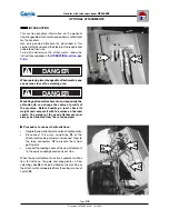
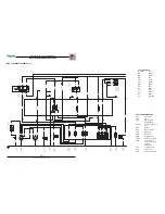
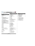
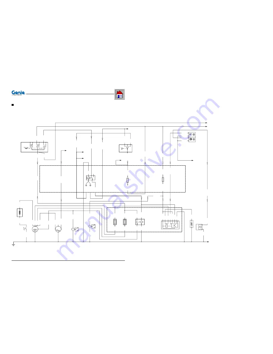
TABLES AND DOCUMENTS ENCLOSED
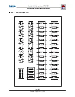
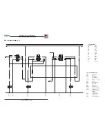
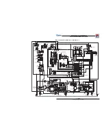
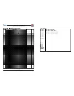
G-3.2 WIRING DIAGRAM tab. 1/8
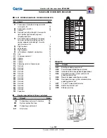
LIST OF ABBREVIATIONS
Label
Description
F##
Fuses
H##
Lamps, lights,
warning lights
HA##
Clacson or back-up
horn
K##
Relays
M##
Motor or pump
P##
Indicators
R##
Resistance
RP##
Potentiometers
SW##
Switches, selectors
SS##
Sensors, micro-
switches, pressure
switches,
transducers
Y##
Solenoid valves
X##
Connectors
A##
Other components
COLOUR TABLE
Acronym
Colour
BK
Black
BN
Brown
RD
Red
OG
Orange
YE
Yellow
GN
Green
BU
Blue
VT
Purple
GY
Grey
WH
White
PK
Pink
TQ
Light blue
SOLENOID V
A
LV
E
ENGINE STOP
ENGINE ST
AR
T
RELA
Y
8/C5
OG/GNø1
OG/GNø1.5
2/F5
87A 87
85
86
BUø1.5
30
K02
BKø1
X5
4
VTø1.5
OG/GNø1
BN/BKø1
CHANGE OVER
SWITCH
4
OGø1
3
F
N
R
F
N
+
PK/BKø1.5
1
R
BN/BKø1.5
3
BNø2.5
F13
PKø1.5
5A
X3
2/C7
PKø1.5
SW03
BNø2.5
X5
OG/GNø1.5
2/C7
1
2
X3
BN/BKø1.5
BU/RDø1
RDø6
BKø50
WH/RDø1.5
24
X2
VT/WHø1.5
P
WH/RDø1
BNø4
4/E8
BU/RDø1
BKø1
SS09
6
X2
GY/BUø1
GY/BUø1
X3
12
RD/BKø1
GY/BUø1
A02
R01
K11
F30
F31
RD/BKø1
H01
Y03
M02
M01
SW2
A01
SW01
CUT
-OFF
4/E2
31
2/A10
2/G10
2/G10
30
15
F5
RESIST
ANCE
GLOW PLUGS
12V BA
TTER
Y
16
X3
X2
23
X3
18
25
X2
VT/WHø1
RD/BKø1
7
X3
5A
WH/RDø1.5
BNø2.5
X2
15
WHø6
L
VT/WHø1
WHø6
WHø6
WH/RDø1
87
86
30
BKø1
BUø1.5
T
50
85
RDø50
RDø6
50A
WHø6
50A
BNø6
BNø6
87 85
30 86
BUø1.5
RDø4
BKø1
BUø4
X2
27
15
30
VTø1.5
BNø4
RDø4
RDø6
ACC 0
ST
IGN
ACC
BAT
IGN
ST
X3
1
A
X1
ADDICTIONAL FUEL
SOLENOID V
A
LV
E
AL
TERNA
TOR
MOTOR
BUø2.5
RDø10
BU/RDø1
B+
W
D+
BUø4
RDø10
ST
AR
TER
BNø6
BNø6
M
BKø50
RDø50
-
+
KEY SWITCH
IGNITION
Y07
WH/RDø1.5
BKø1.5
BA
TTER
Y
PREHEA
TING
GLOW PLUGS
AIR FIL
TER
W
ARNING LIGHT
PROTECTION
SYSTEM
CONTROL UNIT
PREHEA
TING
MAXIFUSE
FUSE
RELA
Y
ST
AR
TING
CONTROL UNIT
PREHEA
TING
AIR FIL
TER
CLOGGING
SENSOR
X3
7


