Service and Repair Manual
April 2017
Repair Procedures
18
GTH-844
Part No. 1272854
About This Section
Most of the procedures in this section should only
be performed by trained service professional in a
suitably equipped workshop. Select the appropriate
repair procedure after troubleshooting the problem.
Perform disassembly procedures to the point where
repairs can be completed. Then to re-assemble,
perform the disassembly steps in reverse order.
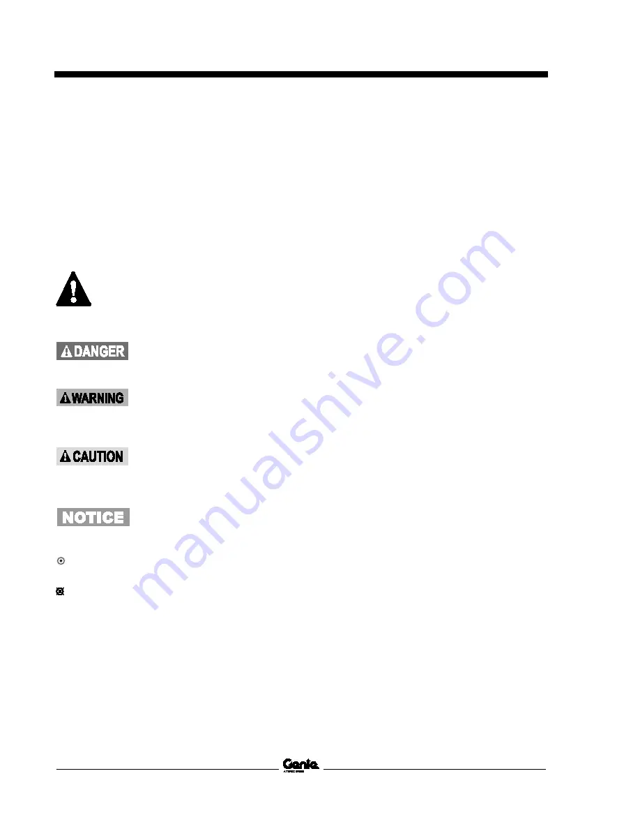
Symbols Legend
Safety alert symbol—used to alert
personnel to potential personal
injury hazards. Obey all safety
messages that follow this symbol
to avoid possible injury or death.
Indicates a imminently hazardous
situation which, if not avoided, will
result in death or serious injury.
Indicates a potentially hazardous
situation which, if not avoided,
could result in death or serious
injury.
Indicates a potentially hazardous
situation which, if not avoided,
may cause minor or moderate
injury.
Indicates a potentially hazardous
situation which, if not avoided,
may result in property damage.
Indicates that a specific result is expected after
performing a series of steps.
Indicates that an incorrect result has occurred
after performing a series of steps.
Summary of Contents for GTH-844
Page 12: ......
Page 61: ...April 2017 Service and Repair Manual Manifolds Part No 1272854 GTH 844 49...
Page 63: ...April 2017 Service and Repair Manual Manifolds Part No 1272854 GTH 844 51...
Page 65: ...April 2017 Service and Repair Manual Manifolds Part No 1272854 GTH 844 53...
Page 67: ...April 2017 Service and Repair Manual Manifolds Part No 1272854 GTH 844 55...
Page 151: ...April 2017 Service and Repair Manual 139 Harness Map Options Work Lights to 15 21456...
Page 155: ...April 2017 Service and Repair Manual 143 Harness Map Options Road Lights to 15 21456...
Page 159: ...April 2017 Service and Repair Manual 147 Harness Map Options Enclosed Cab with Heater...
Page 162: ...Service and Repair Manual April 2017 150 Harness Map Options Enclosed Cab with HVAC...
Page 163: ...April 2017 Service and Repair Manual 151 Electrical Schematic View 1 to 15 20661...
Page 166: ...Service and Repair Manual April 2017 154 Electrical Schematic View 2 to 15 20661...
Page 167: ...April 2017 Service and Repair Manual 155 Electrical Schematic View 1 from 15 20662 to 21456...
Page 170: ...Service and Repair Manual April 2017 158 Electrical Schematic View 2 from 15 20662 to 21456...
Page 171: ...April 2017 Service and Repair Manual 159 Electrical Schematic View 1 from 15 21457 to 21535...
Page 174: ...Service and Repair Manual April 2017 162 Electrical Schematic View 2 from 15 21457 to 21535...
Page 175: ...April 2017 Service and Repair Manual 163 Electrical Schematic View 1 from 15 21536 16E 10000...
Page 178: ...Service and Repair Manual April 2017 166 Electrical Schematic View 2 from 15 21536 16E 10000...
Page 179: ...April 2017 Service and Repair Manual 167 Hydraulic Schematic Single Joystick to 19528...
Page 183: ...April 2017 Service and Repair Manual 171 Hydraulic Schematic Dual Joystick to 19528...


