background image

Genie North America

Genie Australia Pty Ltd.

Genie China

Genie Malaysia

Genie Japan

Genie Korea

Genie Africa

Genie Latin America

Phone

Toll Free

Fax

Phone +

Fax +

Phone +

Fax +

Phone +

Fax +

Phone +

Fax +

Phone +

Fax +

Phone +

Fax +

Phone +

Fax +

425.881.1800
USA and Canada
800.536.1800
425.883.3475

61 7 3375 1660
61 7 3375 1002

86 21 53852570
86 21 53852569

60 4 228 1235
60 4 226 6872

81 3 3453 6082
81 3 3453 6083

82 2 558 7267
82 2 558 3910

27 11 455 0373
27 11 455 0355

55 11 4055 2499
55 11 4043 1661

Genie Holland

Genie Scandinavia

Genie France

Genie Iberica

Genie Germany

Genie U.K.

Genie Mexico City

Phone +

Fax +

Phone +

Fax +

Phone +

Fax +

Phone +

Fax +

Phone +

Fax +

Phone +

Fax +

Phone +

Fax +

31 70 51 78836
31 70 51 13993

46 31 3409612

33 (0)2 37 26 09 99
33 (0)2 37 26 09 98

34 93 579 5042
34 93 579 5059

49 (0)4202 88520
49 (0)4202 8852-20

44 (0)1476 584333
44 (0)1476 584334

52 5 653 03 84
52 5 664 40 16

46 31 3409613

Distributed

By:

Summary of Contents for IWP Super Series

Page 1: ...Operator s Manual Second Edition Fourth Printing Part No 48643 with Maintenance Information ...

Page 2: ...ead understand and obey these safety rules and operating instructions before operating this machine Only trained and authorized personnel shall be permitted to operate this machine This manual is considered a permanent part of your machine and should remain with the machine at all times If you have any questions call Genie Industries Contents Page Safety Rules 1 Controls 7 Legend 8 Pre operation I...

Page 3: ...on contained in this operator s manual 1 Avoid hazardous situations Know and understand the safety rules before going on to the next section 2 Always perform a pre operation inspection 3 Always perform the function tests prior to use 4 Inspect the workplace 5 Only use the machine as it was intended You read understand and obey manufacturer s instructions and safety rules operator s manual and mach...

Page 4: ...200 N Do not use the machine to lift material or equipment The machine is intended to lift personnel and tools to an aerial work site Do not operate the machine near drop offs holes bumps debris unstable or slippery surfaces or other possible hazardous conditions Do not use the machine on a moving or mobile surface or vehicle Do not alter or disable machine components that in any way affect safety...

Page 5: ...rs 0 to 300V Avoid Contact 300V to 50KV 10 3 05 50KV to 200KV 15 4 60 200KV to 350KV 20 6 10 350KV to 500KV 25 7 62 500KV to 750KV 35 10 67 750KV to 1000KV 45 13 72 Do not replace items critical to stability with items of different weight or specification When moving the machine with a forklift or other transport vehicle the platform should be fully lowered the machine should be turned off and no ...

Page 6: ... planning to control the movement of the machine on or near inclines Stay clear of descending platform SAFETY RULES Damaged Machine Hazards Do not use a damaged or malfunctioning machine Be sure all maintenance has been performed as specified in this manual and the Genie IWP Super Series service manual Be sure all decals are in place and legible Be sure the operator s safety and responsibilities m...

Page 7: ...ie product decals use symbols color coding and signal words to identify the following Safety alert symbol used to alert personnel to potential personal injury hazards Obey all safety messages that follow this symbol to avoid possible injury or death Red used to indicate the presence of an imminently hazardous situation which if not avoided will result in death or serious injury Orange used to indi...

Page 8: ... upright position Explosion Hazards Batteries emit explosive gas Keep sparks flames and lighted tobacco away from batteries Charge the battery in a well ventilated area Do not disconnect charger DC output wires from the battery when the charger is on Electrocution Hazards Connect the charger to a grounded AC circuit only Do not expose the battery or charger to water and or rain Before each use ins...

Page 9: ...tform Controls ANSI CSA 1 Interlock display lights four 2 Key switch 3 Red Emergency Stop button 4 Auxiliaryplatformlowering button 5 Powerlight 6 Low battery indicator light for auxiliarylowering 7 DC models Low battery indicator light 8 Control activate button 9 Up Downswitch Platform Controls CE 9 8 9 3 3 4 7 6 1 5 2 ...

Page 10: ...er supply line for machine DC models power to platform 2 Ground controls interlock display 3 Circuit breaker 4 Mast 5 Platform 6 Operator s manual storage container 7 Lifting eye 8 Breather cap 9 Platform controls 10 Bubble level level sensor 24 Power wheel assist option 25 Manual lowering valve located at the bottom of the hydraulic cylinder 26 Battery strap 27 Steer handle power wheel assist opt...

Page 11: ... with a machine before the operator performs the function tests The Pre operation inspection also serves to determine if routine maintenance procedures are required Only routine maintenance items specified in this manual may be performed by the operator Refer to the list on the next page and check each of the items and locations for modifications damage or loose or missing parts A damaged or modif...

Page 12: ...mp o Platform entry mid rail or gate o Sequencing cables and pulleys o Lifting chains and idler wheels o Mast columns and counterweight o Nuts bolts and other fasteners o Breathercap o Foot pads o Adjustable glide pads If equipped Power wheel assist option o Steerhandle o Hydraulic motor and hoses If equipped IWP 20S with Outreach option o Locking bracket o Handle and handle lock o Extension arms ...

Page 13: ... perform this procedure Indicates that new parts will be required to perform this procedure Check the Battery DC Models Proper battery condition is essential to good machine performance and operational safety Improper fluid levels or damaged cables and connections can result in engine component damage and hazardous conditions Electrocution hazard Contact with hot or live circuits could result in d...

Page 14: ...terly inspection before they are put back into service MAINTENANCE Check the Hydraulic Oil Level Maintaining the hydraulic oil at the proper level is essential to machine operation Improper hydraulic oil levels can damage hydraulic components Daily checks allow the inspector to identify changes in oil level that might indicate the presence of hydraulic system problems 1 Be sure the platform is ful...

Page 15: ...lace 5 Only use the machine as it was intended Fundamentals The Function Tests are designed to discover any malfunctions before the machine is put into service The operator must follow the step by step instructions to test all machine functions A malfunctioning machine must never be used If malfunctions are discovered the machine must be tagged and removed from service Repairs to the machine may o...

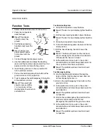
Page 16: ...control activate button and rotate the up down switch in each direction Result The platform up down function should notoperate 18 Push in the red Emergency Stop button at the platform controls and pull out the red Emergency Stop button at the ground controls 19 At the platform controls push in the control activate button and rotate the up down switch in each direction Result The platform up down f...

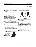
Page 17: ...atform controls Confirm that the interlock display lights and the power light are on 31 Push in the control activate button and rotate the up down switch to the UP position to raise the platform approximately 6 inches 15 cm 32 Activate the manual lowering valve located at the bottom of the hydraulic cylinder Result The platform shouldlower Test Platform Raise and Lower 33 Push in the control activ...

Page 18: ...ess You learn and practice the principles of safe machine operation contained in this operator s manual 1 Avoid hazardous situations 2 Always perform a pre operation inspection 3 Always perform function tests prior to use 4 Inspecttheworkplace Know and understand the workplace inspection before going on to the next section 5 Only use the machine as it was intended Be aware of and avoid the followi...

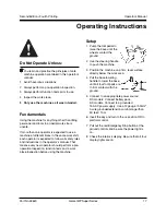
Page 19: ...ator s manual That means every new operator should perform a pre operation inspection function tests and a work place inspection before using the machine Setup 1 Pump the foot pedal to raise the base until the wheels contact the ground 2 Use the steering handle to push the machine 3 Position the machine on a firm level surface directly below the work area 4 Pull the base lowering handle to lower t...

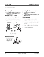
Page 20: ...f travel ANSI CSA CE a control activate button b up down switch Manual Lowering 1 Activate the manual lowering valve located at the bottom of the hydraulic cylinder Auxiliary Platform Lowering 1 Turn the key switch to ground control ifequipped 2 Activate the auxiliary platform lowering button at the ground controls After Each Use 1 Select a safe storage location firm level surface weather protecte...

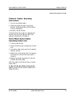
Page 21: ... and reposition the platform Power Wheel Assist Option Operating Instructions 1 Lower the steer handle 2 Pull and hold the function enable lever on either side 3 Activate the thumb rocker switch in the desired direction of travel 4 Release the thumb rocker switch The machine will continue to roll when the rocker switch is released 5 Release the function enable lever to stop the machine and set the...

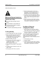
Page 22: ...r switch to the AUTO position 8 Monitor the ampere meter for the correct charge rate The initial charge rate should be approximately 10A The charge rate will decrease as the battery reaches full charge 9 The charger will turn off automatically when the battery is fully charged Set the power switch to the OFF position then disconnect from the AC supply 10 Check the battery acid level when the charg...

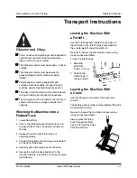
Page 23: ...rklift rings located behind the counterweight under the platform Be sure to inspect the machine and remove any loose or unsecured items To use the forklift rings 1 Raise the platform 3 inches 7 5 cm 2 Position the forklift rings in the up position Loading the Machine With a Crane Use the lifting eye mounted on the rear mast column The battery pack must be removed before lifting the machine with a ...

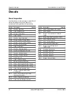
Page 24: ...on Hazard 1 33550 Safety Tape CE 37134 Label Interlock Display 1 37141 Manual Lowering Instructions 1 37143 Notice Max Capacity 300 lbs 136 kg 1 37144 Notice Max Capacity 350 lbs 159 kg 1 37145 Label Manual Lowering Valve 1 38116 Danger Outreach Option Safety Instructions 1 38117 Notice Power Wheel Assist Option Operating Instructions 1 38119 Notice Operating Instructions 1 38122 Label Manual Stor...

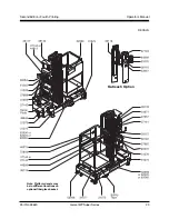
Page 25: ...PartNo 48643 Genie IWP Super Series 23 Operator s Manual Second Edition Fourth Printing DECALS Outreach Option Note Platform decals may be in diffferent locations on optional fiberglass basket ...

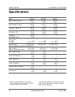
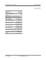
Page 26: ...Serial Plate See Serial Plate See Serial Plate Machine weights vary with option configurations Height stowed 76 in 78 in 76 in 78 in 76 in 78 in base fully lowered base raised 1 9 m 2 0 m 1 9 m 2 0 m 1 9 m 2 0 m Width Standard base 32 in 32 in 81 cm 81 cm Length Standard base 60 in 60 in 1 5 m 1 5 m Width Wide base 40 in 40 in 40 in 1 m 1 m 1 m Length Wide base 60 in 60 in 60 in 1 5 m 1 5 m 1 5 m ...

Page 27: ...m 27 x 26 x 443 4 in gated or sliding mid rail 69 cm x 66 cm x 1 1m Gated ultra narrow platform 22 x 18 x 443 4 in 56 cm x 46 cm x 1 1 m Gated narrow platform 26 x 20 x 443 4 in 66 cm x 51 cm x 1 1 m Standard fiber platform 29 x 261 2 x 431 2 in 74 cm x 67 cm x 1 1 m Narrow fiber platform 26 x 22 x 431 2 in 66 cm x 56 cm x 1 1 m Front entry gated narrow platform 20 x 26 x 443 4 in 51cm x 66 cm x 1...

Page 28: ...5 60 4 226 6872 81 3 3453 6082 81 3 3453 6083 82 2 558 7267 82 2 558 3910 27 11 455 0373 27 11 455 0355 55 11 4055 2499 55 11 4043 1661 Genie Holland Genie Scandinavia Genie France Genie Iberica Genie Germany Genie U K Genie Mexico City Phone Fax Phone Fax Phone Fax Phone Fax Phone Fax Phone Fax Phone Fax 31 70 51 78836 31 70 51 13993 46 31 3409612 33 0 2 37 26 09 99 33 0 2 37 26 09 98 34 93 579 5...

Reviews: