background image

Section 3 • Scheduled Maintenance Procedures

REV B

September 2016

3 - 18

GRC

Part No. 227123

CHECKLIST

B

PROCEDURES

B-10
Test the Drive Speed -
Raised Position

Genie specifications require that this procedure be
performed every 250 hours or quarterly, whichever
comes first.

Proper drive functions are essential to safe
machine operation. The drive function should
respond quickly and smoothly to operator control.
Drive performance should also be free of
hesitation, jerking and unusual noise over the
entire proportionally controlled speed range.

Note: Perform this procedure with the machine on
a firm, level surface that is free of obstructions.

1 Create start and finish lines by marking two

lines on the ground 40 feet / 12.2 m apart.

2 Turn the key switch to platform control and pull

out the red Emergency Stop button to the on
position at both the ground and platform
controls.

3 Press and hold the high or low speed lift enable

button.

4 Press the platform up button.

5 Raise the platform approximately 4 feet / 1.2 m

from the ground.

6 Choose a point on the machine; i.e., contact

patch of a tire, as a visual reference for use
when crossing the start and finish lines.

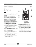
7 Press and hold the drive/steer function enable

switch on the control handle.

a

drive/steer function enable switch

b

platform up button

c

low speed lift enable button

d

high speed lift enable button

e

blue arrow

8 Move the control handle in the direction

indicated by the blue arrow on the control panel
until the machine begins to move forward.

9 Bring the machine to top drive speed before

reaching the start line. Begin timing when the
selected reference point on the machine
crosses the start line.

10 Continue at full speed and note the time when

your reference point on the machine passes the
finish line. Refer to Section 2, 

Specifications

.

Summary of Contents for Lift Guard GRC-12

Page 1: ...Service Manual Part No 227123 Rev B1 September 2016 GRC 12 Serial Number Range from GRC11 1000 to GRC16 2369 from GRC16P 2370 to GRC16P 4599 from GRCP 4600 ...

Page 2: ... Genie has endeavored to deliver the highest degree of accuracy possible However continuous improvement of our products is a Genie policy Therefore product specifications are subject to change without notice Readers are encouraged to notify Genie of errors and send in suggestions for improvement All communications will be carefully considered for future printings of this and all other manuals Copy...

Page 3: ...1234 2 1 4 3 5 6 Model Serial number Elec Hydr Schematic Year of Manufacture Power supply voltage Pneumatic Pressure Maximum Wind Speed Maximum allowable inclination of the chassis Gradeability Maximum platform height Maximum allowable side force Machine unladen weight Max Load Occupants and Equipment must not exceed Indoor Outdoor Nominal Power GRP 12345 2016 GR P 12345 2 1 3 4 5 To August 31 201...

Page 4: ...September2016 GRC Part No 227123 This page intentionally left blank iv ...

Page 5: ...perator s manual are also safety hazards when maintenance and repair procedures are performed Do Not Perform Maintenance Unless You are trained and qualified to perform maintenance on this machine You read understand and obey manufacturer s instructions and safety rules employer s safety rules and worksite regulations applicable governmental regulations You have the appropriate tools lifting equip...

Page 6: ... is properly ventilated and well lit Personal Safety Any person working on or around a machine must be aware of all known safety hazards Personal safety and the continued safe operation of the machine should be your top priority Read each procedure thoroughly This manual and the decals on the machine use signal words to identify the following Safety alert symbol used to alert personnel to potentia...

Page 7: ... Specifications 2 2 Manifold Component Specifications 2 3 Hydraulic Hose and Fitting Torque Specifications 2 4 SAE and Metric Fasteners Torque Charts 2 6 Section 3 Rev Scheduled Maintenance Procedures Introduction 3 1 Pre delivery Preparation Report 3 3 Maintenance Inspection Report 3 5 A Checklist A Procedures A 1 Inspect the Manuals and Decals 3 6 A 2 Perform Pre operation Inspection 3 7 A 3 Per...

Page 8: ...pped 3 15 B 8 Test the Drive Brakes 3 16 B 9 Test the Drive Speed Stowed Position 3 17 B 10 Test the Drive Speed Raised Position 3 18 B 11 Test the Slow Drive Speed 3 19 B 12 Test the Flashing Beacons 3 20 B 13 Test the Motion Alarm if equipped 3 20 B 14 Perform Hydraulic Oil Analysis 3 22 B 15 Inspect the Breather Cap 3 22 B 16 Inspect the Electrical Contactor 3 23 A Checklist C Procedures C 1 Re...

Page 9: ...rm 4 4 1 4 Platform Emergency Stop Button 4 5 A Ground Controls 2 1 Software Revision Level 4 7 2 2 Machine Setup 4 8 2 3 Level Sensor 4 9 A Hydraulic Pump 3 1 Function Pump 4 12 A Function Manifold 4 1 Function Manifold Components 4 14 4 2 Valve Adjustments Function Manifold 4 16 4 3 Valve Coils 4 20 A Brake Release Hand Pump Components 5 1 Brake Release Hand Pump Components 4 22 ix ...

Page 10: ...xle Components 7 1 Yoke and Drive Motor 4 24 7 2 Steer Cylinder 4 26 7 3 Steer Bellcrank 4 26 A Non steer Axle Components 8 1 Drive Brake 4 27 A Platform Components 9 1 Platform 4 28 9 2 Platform Extension 4 28 A Mast Components 10 1 Mast 4 30 10 2 Wear Pads 4 41 10 3 Lift Cylinder 4 42 10 4 Lift Cylinder Wear Block 4 44 10 5 Mast Coil Cord 4 44 ...

Page 11: ... Faults 5 9 A Type UXXX Faults 5 10 A Type FXXX Faults 5 11 A Type CXXX Faults 5 12 Section 6 Rev Schematics Introduction 6 1 B Electrical Component and Wire Color Legends 6 2 B Wiring Diagram Ground and Platform Controls 6 3 B Electrical Symbols Legend 6 4 B Electrical Schematic from serial number GRC11 1000 to GRC11 1078 6 6 B Electrical Schematic from serial number GRC11 1079 6 10 A Hydraulic C...

Page 12: ...September2016 GRC Part No 227123 This page intentionally left blank ...

Page 13: ...y maximum 200AH Reserve capacity 25A rate 380 minutes DC Motor Voltage 24 V Horse Power 4 5 HP 2950 RPM Kilowatts 3 3 kW 2950 RPM Fluid capacities Hydraulic tank 1 5 gallons 5 7 liters Hydraulic system 2 2 gallons including tank 8 3 liters For operational specifications refer to the Operator s Manual Tires and wheels Height stowed maximum GRC 12 66 8 in 1 69 m Tires and wheels Tire size solid rubb...

Page 14: ...13 Water content maximum 200 ppm Chevron Rykon MV oil is fully compatible and mixable with Shell Donax TG Dexron III oils Genie specifications require hydraulic oils which are designed to give maximum protection to hydraulic systems have the ability to perform over a wide temperature range and the viscosity index should exceed 140 They should provide excellent antiwear oxidation corrosion inhibiti...

Page 15: ...4 Nm SAE No 8 50 ft lbs 68 Nm SAE No 10 55 ft lbs 75 Nm SAE No 12 75 ft lbs 102 Nm Valve Coil Resistance Note The following coil resistance specifications are at an ambient temperature of 68 F 20 C As valve coil resistance is sensitive to changes in air temperature the coil resistance will typically increase or decrease by 4 for each 18 F 7 7 C that your air temperature increases or decreases from...

Page 16: ... Thread Size Flats 4 7 16 20 2 6 9 16 18 1 1 4 8 3 4 16 1 10 7 8 14 1 12 1 1 16 12 1 16 1 5 16 12 1 20 1 5 8 12 1 24 1 7 8 12 1 SAE O ring Boss Port tube fitting installed into Aluminum SAE Dash size Torque 4 11 ft lbs 14 9 Nm 6 23 ft lbs 31 2 Nm 8 40 ft lbs 54 2 Nm 10 69 ft lbs 93 6 Nm 12 93 ft lbs 126 1 Nm 16 139 ft lbs 188 5 Nm 20 172 ft lbs 233 2 Nm 24 208 ft lbs 282 Nm SAE O ring Boss Port tu...

Page 17: ...e 1 a hydraulic hose b hex nut c reference mark d body hex fitting b c a d Torque Procedure JIC 37 fittings 1 Align the tube flare hex nut against the nose of the fitting body body hex fitting and tighten the hex nut to the body hex fitting to hand tight approximately 30 in lbs 3 4 Nm 2 Make a reference mark on one of the flats of the hex nut and continue it on to the body hex fitting with a perma...

Page 18: ...in lbs N m in lbs N m in lbs N m in lbs N m in lbs N m 20 80 9 100 11 3 110 12 4 140 15 8 130 14 7 28 90 10 1 120 13 5 120 13 5 160 18 140 15 8 ft lbs N m ft lbs N m ft lbs N m ft lbs N m ft lbs N m 18 13 17 6 17 23 18 24 25 33 9 21 28 4 24 14 19 19 25 7 20 27 1 27 36 6 24 32 5 16 23 31 2 31 42 33 44 7 44 59 6 38 51 5 24 26 35 2 35 47 4 37 50 1 49 66 4 43 58 3 14 37 50 1 49 66 4 50 67 8 70 94 7 61...

Page 19: ... in the stowed position Key switch in the off position with the key removed The red Emergency Stop button in the off position at both ground and platform controls Wheelschocked All external AC power supply disconnected from the machine About This Section This section contains detailed procedures for each scheduled maintenance inspection Each procedure includes a description safety warnings and ste...

Page 20: ...on report to use for each inspection Store completed forms as required Maintenance Schedule There are five types of maintenance inspections that must be performed according to a schedule daily quarterly semi annually annually and two year The Scheduled Maintenance Procedures Section and the Maintenance Inspection Report have been divided into five subsections A B C D and E Use the following chart ...

Page 21: ... Use this form to record the results Place a check in the appropriate box after each part is completed Follow the instructions in the operator s manual If any inspection receives an N remove the machine from service repair and reinspect it After repair place a check in the R box Legend Y yes completed N no unable to complete R repaired Comments Fundamentals It is the responsibility of the dealer t...

Page 22: ...Section 3 Scheduled Maintenance Procedures September2016 3 4 GRC Part No 227123 This page intentionally left blank ...

Page 23: ...Function tests Perform after 40 hours A 4 30 day service Perform every 100 hours A 5 Grease steer yokes Instructions Make copies of this report to use for each inspection Select the appropriate checklist s for the type of inspection to be performed Daily or 8 hours Inspection A Quarterly or 250 hours Inspection A B Semi annually or 500 hours Inspection A B C Annually or 1000 hours Inspection A B C...

Page 24: ... operator s and safety manuals are present and complete in the storage container on the platform 2 Examine the pages of each manual to be sure that they are legible and in good condition Result The operator s manual is appropriate for the machine and all manuals are legible and in good condition Result The operator s manual is not appropriate for the machine or all manuals are not in good conditio...

Page 25: ...ction also serves to determine if routine maintenance procedures are required Complete information to perform this procedure is available in the appropriate operator s manual Refer to the Operator s Manual on your machine A 3 Perform Function Tests Completing the function tests is essential to safe machine operation Function tests are designed to discover any malfunctions before the machine is put...

Page 26: ...eturn Filter A 5 Grease the Steer Yokes Genie specifications require that this procedure be performed every 100 hours of operation Regular application of lubrication to the steer yokes is essential to good machine performance and service life Continued use of an insufficiently greased steer yoke will result in component damage 1 Locate the grease fitting on the top of the steer yoke 2 Pump multipu...

Page 27: ...ize battery acid spills with baking soda and water 1 Raise the platform approximately 3 feet 1 m 2 Open the battery cover Rest the cover against the chassis 3 Lower the platform until the mast just contacts the battery cover Crushing hazard Keep hands clear of the battery cover when lowering the platform 4 Be sure that the battery cable connections are free of corrosion Note Adding terminal protec...

Page 28: ...ry cell with a hydrometer Note the results 13 Check the ambient air temperature and adjust the specific gravity reading for each cell as follows Add 0 004 to the reading of each cell for every 10 5 5 C above 80 F 26 7 C Subtract 0 004 from the reading of each cell for every 10 5 5 C below 80 F 26 7 C Result All battery cells display a specific gravity of 1 277 0 007 The battery is fully charged Pr...

Page 29: ...nections at the fuse and battery The charger will then operate correctly and begin charging the batteries If simultaneously the charger alarm sounds and the LEDs blink two times the input voltage is too low or too high Correct the voltage issue The charger will then operate correctly and begin charging the batteries If simultaneously the charger alarm sounds and the LEDs blink three times the char...

Page 30: ...ing 3 Inspect the following areas for burnt chafed corroded and loose wires Ground control panel Hydraulic power unit 4 Inspect for a liberal coating of dielectric grease in all wiring connections between the ECM and the platform controls and level sensor wiring 5 Turn the key switch to ground control and pull out the red Emergency Stop button to the on position at both the ground and platform con...

Page 31: ...ever comes first A properly functioning Emergency Stop is essential for safe machine operation An improperly operating red Emergency Stop button will fail to shut off power and stop all machine functions resulting in a hazardous situation Note As a safety feature selecting and operating the ground controls will override the platform controls except the platform red Emergency Stop button 1 Turn the...

Page 32: ... 3 Check the platform up down function from the ground controls Result The machine functions should not operate 4 Turn the key switch to ground control 5 Check the machine functions from the platform controls Result The machine functions should not operate 6 Turn the key switch to the off position 7 Test the machine functions from the ground and platform controls Result No machine functions should...

Page 33: ...ack wire to battery negative The inverter will then operate correctly and begin supplying AC power If the right fault LED 123 blinks one time the power draw is too high The tool being used requires too much power to operate or is being used at or near the limit of the inverter for an extended period of time Reduce the power draw The inverter will then operate correctly and begin supplying AC power...

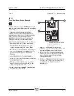
Page 34: ...2 Turn the key switch to platform control and pull out the red Emergency Stop button to the on position at both the ground and platform controls 3 Lower the platform to the stowed position 4 Choose a point on the machine i e contact patch of a tire as a visual reference for use when crossing the test line 5 Press and hold the drive steer function enable switch on the control handle a drive steer f...

Page 35: ...rgency Stop button to the on position at both the ground and platform controls 3 Lower the platform to the stowed position 4 Choose a point on the machine i e contact patch of a tire as a visual reference for use when crossing the test line 5 Check to make sure the low drive speed light is off If the low dive speed light is on press the drive speed select button to turn off the low drive speed fun...

Page 36: ...top button to the on position at both the ground and platform controls 3 Press and hold the high or low speed lift enable button 4 Press the platform up button 5 Raise the platform approximately 4 feet 1 2 m from the ground 6 Choose a point on the machine i e contact patch of a tire as a visual reference for use when crossing the start and finish lines 7 Press and hold the drive steer function ena...

Page 37: ...trol and pull out the red Emergency Stop button to the on position at both the ground and platform controls 3 Lower the platform to the stowed position 4 Press the drive speed select button until the low drive speed light is on 5 Choose a point on the machine i e contact patch of a tire as a visual reference for use when crossing the start and finish lines 6 Press and hold the drive steer function...

Page 38: ...the Motion Alarm if equipped Genie specifications require that this procedure be performed every 250 hours or quarterly whichever comes first Alarms are used to alert operators and ground personnel of machine proximity and motion The motion alarm is located in the ground control box and when activated will sound at 60 beeps per minute 1 Turn the key switch to ground control and pull out the red Em...

Page 39: ...form is lowered 15 Press and hold the low speed lift enable button 16 Press the platform up button and raise the platform approximately 4 feet 1 2 m Result The motion alarm should sound when the platform is raised 17 Press and hold the low speed lift enable button 18 Press the platform down button and lower the platform to the stowed position Result The motion alarm should sound when the platform ...

Page 40: ...inspection test the oil quarterly Replace the oil when it fails the test See E 1 Test or Replace the Hydraulic Oil B 15 Inspect the Breather Cap Genie specifications require that this procedure be performed every 250 hours or quarterly whichever comes first A free breathing hydraulic tank cap is essential for good machine performance and service life A dirty or clogged cap may cause the machine to...

Page 41: ... controls turn the key switch to the off position 2 Push in the red Emergency Stop button at the ground controls to the off position 3 At the non steer end of the machine open the cover to access the electrical tray 4 Locate and disconnect the Anderson connector 5 Locate the electrical contactor mounted on the fuse bracket 6 Visually inspect the contact points of the contactor for the following it...

Page 42: ...hine fails to lift the maximum rated load The hydraulic tank is a vented type tank The breather cap has an internal air filter that can become clogged or over time can deteriorate If the breather cap is faulty or improperly installed impurities can enter the hydraulic system which may cause component damage Extremely dirty conditions may require that the cap be inspected more often 1 Remove and di...

Page 43: ...ote The hydraulic tank return filter is mounted on the function manifold next to the hydraulic power unit 1 Clean the area around the oil filter Remove the filter with an oil filter wrench 2 Apply a thin layer of oil to the new oil filter gasket 3 Install the new filter and tighten it securely by hand 4 Use a permanent ink marker to write the date and number of hours from the hour meter onto the f...

Page 44: ... result in death or serious injury Remove all rings watches and other jewelry 2 Open the power unit module tray 3 Tag and disconnect the hydraulic tank return hard line from the hydraulic filter head and remove the hard line from the tank Cap the fitting on the filter head 4 Tag and disconnect the hydraulic pump inlet hard line and remove the hard line from the tank Cap the fitting on the pump 5 R...

Page 45: ...ulic filter head and torque to specification Refer to Section 2 Specifications 12 Fill the tank with hydraulic oil until the fluid is at the FULL indicator on the hydraulic tank Do not overfill 13 Activate the pump to fill the hydraulic system with oil and bleed the system of air Component damage hazard The pump can be damaged if operated without oil Be careful not to empty the hydraulic tank whil...

Page 46: ...Section 3 Scheduled Maintenance Procedures September2016 3 28 GRC Part No 227123 This page intentionally left blank ...

Page 47: ...ff position at both ground and platform controls Wheelschocked All external AC power supply disconnected from the machine About This Section Most of the procedures in this section should only be performed by a trained service professional in a suitably equipped workshop Select the appropriate repair procedure after troubleshooting the problem Perform disassembly procedures to the point where repai...

Page 48: ...tform controls circuit board U3 c proportional control handle and drive steer enable switch JC9 d alarm H1 Operational Indicator Codes These codes are generated by the electrical system to indicate machine operating status During normal operation a code will appear in the platform controls LED readout if a condition such as off level chassis mode operation or pothole guards stuck occurs If the pla...

Page 49: ...ld result in death or serious injury Remove all rings watches and other jewelry Component damage hazard Electrostatic discharge ESD can damage printed circuit board components Maintain firm contact with a metal part of the machine that is grounded at all times when handling printed circuit boards OR use a grounded wrist strap PLATFORM CONTROLS 9 Carefully remove the platform controls circuit board...

Page 50: ...when handling printed circuit boards OR use a grounded wrist strap 7 Carefully remove the joystick fasteners 8 Carefully remove the joystick from the platform control box Torque specifications Joystick fasteners 9 in lbs 1 Nm 1 3 Platform Controls Alarm How to Remove the Platform Controls Alarm 1 Push in the red Emergency Stop button to the off position at both the ground and platform controls 2 D...

Page 51: ... the control box 5 Disconnect the white wires from the Emergency Stop base Electrocution burn hazard Contact with electrically charged circuits could result in death or serious injury Remove all rings watches and other jewelry Component damage hazard Electrostatic discharge ESD can damage printed circuit board components Maintain firm contact with a metal part of the machine that is grounded at al...

Page 52: ...e platform to be raised or lowered at the ground controls Note Steer and drive functions are not available at the ground controls When the ECM is in the set up mode the ground controls are used to adjust the function speed parameters machine models or machine options For further information or assistance consult the Genie Industries Service Department a circuit breaker CB2 b red Emergency Stop P1 ...

Page 53: ...rols will show CH See example below Result The display at the ground controls will show the machine model and hour meter information See example below 2 Press the ground controls scroll down button Result The ground controls LED display will indicate the software revision and hour meter information After 5 seconds the ground controls LED display will display machine model and hour meter informatio...

Page 54: ...ocedure must only be performed by a trained service professional Attempting this procedure without the necessary skills could result in death or serious injury Note Select a test area that is firm level and free of obstructions 1 Turn the key switch to the ground controls position and pull out the red Emergency Stop button to the on position at the platform controls 2 Press and hold the ground con...

Page 55: ...procedure with the machine on a firm level surface free of obstructions Note Perform this procedure with the platform in the stowed position If you are not installing a new level sensor proceed to step 6 1 Tag and disconnect the level sensor wire harness from the chassis wire harness 2 Remove the level sensor adjusting fasteners Remove the level sensor from the machine 3 Place the new level sensor...

Page 56: ... should not sound 8 Center a lifting jack under the drive chassis at the ground controls side of the machine 9 Raise the machine approximately 2 inches 5 cm 10 Place a 0 65 x 6 x 6 inch 1 65 x 15 x 15 cm thick steel block under both wheels at the ground controls side of the machine 11 Lower the machine onto the blocks 12 Raise the platform approximately 1 foot 30 cm Result The level sensor alarm s...

Page 57: ... Raise the platform approximately 1 foot 30 cm Result The level sensor alarm should not sound Result The level sensor alarm does sound The level sensor is faulty and must be replaced Repeat this procedure beginning with step 1 31 Raise the machine slightly 32 Remove the blocks from under both wheels 33 Lower the machine and remove the jack 34 Center a lifting jack under the drive chassis at the no...

Page 58: ...on the pump 3 Turn the key switch to ground control and pull out the red Emergency Stop button to the on position at both the ground and platform controls 4 Activate the platform up function from the ground controls Result If the pressure gauge reads 3200 psi 221 bar immediately stop The pump is good Result If pressure fails to reach 3200 psi 221 bar the pump is bad and will need to be serviced or...

Page 59: ...ag disconnect and plug the high pressure hose at the pump Cap the fitting on the pump Bodily injury hazard Spraying hydraulic oil can penetrate and burn skin Loosen hydraulic connections very slowly to allow the oil pressure to dissipate gradually Do not allow oil to squirt or spray 3 Remove the pump mounting bolts Carefully remove the pump Tip over hazard After replacing the hydraulic pump it is ...

Page 60: ...heck valve 10 psi 0 7 bar D Drive circuit 20 ft lbs 27 Nm 5 Solenoid valve 3 position 4 way E Drive forward reverse 25 ft lbs 34 Nm 6 Solenoid valve 3 position 4 way F Steer left right 25 ft lbs 34 Nm 7 Flow regulator and relief valve 0 75 gpm 2 8 L min 1500 psi 103 bar G Steer circuit 26 ft lbs 35 Nm 8 Solenoid valve 2 position 4 way H Platform up 25 ft lbs 34 Nm 9 Relief valve 3500 psi 241 bar m...

Page 61: ...rt No 227123 GRC 4 15 FUNCTION MANIFOLD A B C D E F G H I Y8 Y4 Y3 Y5 Y6 Note alpha callouts refer to corresponding notes on the hydraulic schematic Note alpha numeric callouts refer to corresponding notes on the electrical schematic 1 2 5 6 7 8 9 3 4 ...

Page 62: ...on enable switch 7 Move and hold the joystick fully in either direction while observing the pressure reading on the pressure gauge Note the pressure Refer to Section 2 Specifications 8 Turn the machine off Hold the system relief valve with a wrench and remove the cap schematic item I 9 Adjust the internal hex socket Turn it clockwise to increase the pressure or counterclockwise to decrease the pre...

Page 63: ...e or counterclockwise to decrease the pressure Tip over hazard Failure to adjust the relief valves to specification could result in the machine tipping over causing death or serious injury Do not adjust the relief valve pressures higher than specifications 10 Install the relief valve cap 11 Repeat steps 4 through 7 to confirm the relief valve pressure 12 Place maximum rated load into the platform ...

Page 64: ...eight from the platform 21 Bleed the hydraulic system by raising the platform to full height If the pump cavitates or the platform fails to reach full height add hydraulic oil until the pump is functioning correctly Do not overfill the hydraulic tank Component damage hazard Do not continue to operate the machine if the hydraulic pump is cavitating How to Adjust the Steer Relief Valve Note Be sure ...

Page 65: ...pressure Refer to Section 2 Specifications 6 Press and hold the steer thumb rocker switch to the left Allow the wheels to completely turn to the left Continue holding the switch while observing the pressure reading on the pressure gauge 7 Turn the machine off Hold the steer relief valve with a wrench and remove the cap schematic item G 8 Adjust the internal hex socket Turn it clockwise to increase...

Page 66: ...itical to normal operation is continuity within the coil Zero resistance or infinite resistance indicates the coil has failed Since coil resistance is sensitive to temperature resistance values outside specification can produce erratic operation When coil resistance decreases below specification amperage increases As resistance rises above specification voltage increases While valves may operate w...

Page 67: ...ead 9V DC or more when measured across the terminals Resistor 10Ω Ω Ω Ω Ω Genie part number 27287 3 Set a multimeter to read DC amperage Note The multimeter when set to read DC amperage should be capable of reading up to 800 mA 4 Connect the negative lead to the other terminal on the coil Note If testing a single terminal coil connect the negative lead to the internal metallic ring at either end o...

Page 68: ... brake release 30 ft lbs 41 Nm 2 Needle valve pilot operated K Manual brake release enable 45 50 in lbs 5 Nm Brake Release Hand Pump Components 5 1 Brake Release Hand Pump Components The brake release hand pump manifold is mounted behind the hydraulic power unit J K Note alpha callouts refer to corresponding notes on the hydraulic schematic 1 2 ...

Page 69: ...tion Refer to Section 2 Hydraulic Hose and Fitting Torque Specifications Note Perform this procedure with the platform in the stowed position 1 Tag disconnect and plug the hydraulic supply hard line at the pump Cap the fitting on the pump Remove the hard line from the tank Hydraulic Tank 2 Tag disconnect and plug the return hard line at the hydraulic filter Cap the fitting on the filter Bodily inj...

Page 70: ...is could fall if not properly supported 6 Remove the wheel castle nut Remove the wheel 7 Tag disconnect and plug the hydraulic hoses on the drive motor Cap the fittings on the drive motor Bodily injury hazard Spraying hydraulic oil can penetrate and burn skin Loosen hydraulic connections very slowly to allow the oil pressure to dissipate gradually Do not allow oil to squirt or spray Component dama...

Page 71: ...nder the chassis for support Crushing hazard The chassis could fall if not properly supported 6 Remove the wheel castle nut Remove the wheel 7 Tag disconnect and plug the hydraulic hoses on the drive motor Cap the fittings on the drive motor Bodily injury hazard Spraying hydraulic oil can penetrate and burn skin Loosen hydraulic connections very slowly to allow the oil pressure to dissipate gradua...

Page 72: ...ulic oil can penetrate and burn skin Loosen hydraulic connections very slowly to allow the oil pressure to dissipate gradually Do not allow oil to squirt or spray Component damage hazard Hoses can be damaged if they are kinked or pinched 7 3 Steer Bellcrank How to Remove the Steer Bellcrank 1 Remove the steer cylinder See 7 2 How to Remove the Steer Cylinder 2 Center a lifting jack under the drive...

Page 73: ...achine approximately 2 inches 5 cm Place blocks under the chassis for support Crushing hazard The chassis could fall if not properly supported 6 Remove the wheel castle nut Remove the wheel 7 Tag disconnect and plug the hydraulic hose from the brake Cap the fitting on the brake Bodily injury hazard Spraying hydraulic oil can penetrate and burn skin Loosen hydraulic connections very slowly to allow...

Page 74: ... the side Remove the platform from the machine Crushing hazard The platform could become unbalanced and fall when removed from the machine A properly centered lifting strap is essential when removing the platform from the machine Note During removal the overhead crane strap will need to be carefully adjusted for proper balancing 9 2 Platform Extension How to Remove the Platform Extension Deck 1 Re...

Page 75: ...t around the extension deck railing Remove the extension deck from the machine Crushing hazard The extension deck could become unbalanced and fall when removed from the machine A properly centered lifting strap is essential when removing the extension deck from the machine Note During removal the overhead crane strap will need to be carefully adjusted for proper balancing ...

Page 76: ...tions Note Perform this procedure on a firm level surface Note Perform this procedure with the mast in the stowed position 1 Remove the Platform See 9 1 How to Remove the Platform 2 Tag and disconnect the power to platform wire harness at the quick disconnect near the Electronic Control Module ECM 3 Tag and disconnect the up limit switch cable near the Electronic Control Module ECM Mast Components...

Page 77: ...ions very slowly to allow the oil pressure to dissipate gradually Do not allow oil to squirt or spray 9 Remove the fasteners securing the top mast cover to the top of the mast Set the cover and fasteners to the side 10 Using an overhead crane attach a sling equipped with the appropriate sized hooks to the lifting eyes located inside the mast assembly Support the mast Do not apply any lifting press...

Page 78: ...f of the mast and remove the work trays Set the trays and the fasteners to the side 7 Remove the fasteners securing the down limit switch assembly to the limit switch bracket and remove the limit switch assembly Set the limit switch assembly and the fasteners to the side 8 With the chassis mount side up stagger the mast assembly to gain access to the rivets securing the inner wear pads to the bott...

Page 79: ...a wear pads b rivets c number 4 mast d number 3 mast e number 2 mast f number 1 mast 12 Using a drill carefully drill out the rivets securing the number 3 outer wear pads to the top half of the number 3 mast section Refer to Illustration 2 Note While drilling the rivets out be careful not drill into the number 2 mast section Note While drilling the rivets out be careful not enlarge the wear pad mo...

Page 80: ...the rivets out be careful not enlarge the wear pad mounting holes 17 Using a drill carefully drill out the rivets securing the number 3 inner wear pads to the bottom half of the number 3 mast section Refer to Illustration 5 Illustration 5 a number 3 mast b rivet c wear pads d number 1 mast e number 2 mast Note While drilling the rivets out be careful not drill into the number 2 mast section Note W...

Page 81: ...mounting holes 21 Using a drill carefully drill out the rivets securing the number 2 inner wear pads to the bottom half of the number 2 mast section Refer to Illustration 7 Illustration 7 a number 3 mast b rivet c wear pads d number 1 mast e number 2 mast Note While drilling the rivets out be careful not drill into the number 1 mast section Note While drilling the rivets out be careful not enlarge...

Page 82: ...usted for proper balancing 3 Secure the number 1 mast to the work table 4 Using the appropriate rivets securely install the upper corner wear pads to the upper half of the number 1 mast Refer to Illustration 1 Illustration 1 a wear pad b rivet c number 1 mast 5 Attach a lifting strap from an overhead crane to the number 2 mast and carefully slide the number 2 mast onto the number 1 mast with the c...

Page 83: ...mber 2 mast access holes and to the number 1 mast rivet holes Refer to Illustration 3 10 Using the appropriate rivets securely install the lower corner wear pads to the lower half of the number 1 mast Refer to Illustration 3 Note After installing the first rivet move and align the number 2 mast access hole to the second hole on the wear pad and install the second rivet Refer to Illustration 3 Illu...

Page 84: ...r 3 mast b rivet c wear pads d number 1 mast e number 2 mast 14 Slide the number 3 mast towards the bottom of the number 2 mast and align the lower number 3 mast access holes to the lower number 2 rivet holes Refer to Illustration 6 15 Working at the top of the number 3 mast carefully slide the lower corner wear pads between the number 3 mast and the number 2 mast Refer to Illustration 6 16 Align ...

Page 85: ... with the cylinder mount brackets facing the work table Crushing hazard The number 4 mast could become unbalanced and fall if not properly supported Note During installation the overhead crane strap will need to be carefully adjusted for proper balancing 20 Slide the lower inner corner wear pads between the number 4 mast and the number 3 mast Align the holes on the wear pads to the rivet holes on ...

Page 86: ... and install the second rivet Refer to Illustration 9 Illustration 9 a wear pad b rivets c number 4 mast d number 3 mast e number 2 mast f number 1 mast 25 Attach a lifting strap from an overhead crane to the mast assembly and carefully rotate the mast 180 Set the mast assembly onto the work table and secure the mast to the table Crushing hazard The mast assembly could become unbalanced and fall i...

Page 87: ...ift cylinder 32 Install the hair pin clips onto each side of the mast cylinder pin 33 Securely install the lift cylinder retaining bolt onto the lower cylinder block Do not over tighten the bolt 34 Using the appropriate fasteners install the limit switch assembly onto the lower half of the mast assembly Do not over tighten the fasteners Refer to Illustration 10 35 Securely install the hydraulic li...

Page 88: ...embly or fitting the O ring on the fitting and or hose end must be replaced and then torqued to specification during installation Refer to Section 2 Hydraulic Hose and Fitting Torque Specifications 1 Remove the mast See 10 1 How to Remove the Mast Assembly 2 Remove the nylock nuts securing the lift cylinder to the cylinder mast mount brackets located inside the top half of the mast assembly Set th...

Page 89: ... overhead crane to the cylinder and carefully slide the lift cylinder out of the mast assembly Crushing hazard The lift cylinder could become unbalanced and fall if not properly supported when removed from the mast Note During removal the overhead crane strap will need to be carefully adjusted for proper balancing a lower mast assembly b lift cylinder c hydraulic hose d hair pin clip e mast cylind...

Page 90: ...r 2 cylinder d number 1 cylinder e cylinder wear block 10 5 Mast Coil Cord How to Remove the Mast Coil Cord Bodily injury hazard This procedure requires specific repair skills lifting equipment and a suitable workshop Attempting this procedure without these skills and tools could result in death or serious injury and significant component damage Dealer service is strongly recommended 1 Remove the ...

Page 91: ...njury hazard Spraying hydraulic oil can penetrate and burn skin Loosen hydraulic connections very slowly to allow the oil pressure to dissipate gradually Do not allow oil to squirt or spray Diagnostics Observe and Obey Troubleshootingandrepairproceduresshallbe completed by a person trained and qualified on the repair of this machine Immediately tag and remove from service a damaged or malfunctioni...

Page 92: ...machine by pinpointing the area or component affected Definitions GSDS acronym for Genie SmartLink Diagnostic System ECM acronym for Electronic Control Module GCON acronym for Ground Controls PCON acronym for Platform Controls OIC acronym for Operational Indicator Codes DTC acronym for Diagnostic Trouble Codes TM Genie SmartLink Diagnostic System This machine is equipped with the Genie SmartLink D...

Page 93: ...8 BL QD32 03 Switch Sensor Power Digital Output 14 RD QD32 04 Automotive Horn Digital Output 18 WH QD32 05 Pothole Limit Switch Digital Input 18 OR RD QD32 06 Machine ID GR Select Digital Input 18 RD QD32 07 Down Limit Switch Digital Input 18 OR QD32 08 Level Sensor Digital Input 18 RD BK QD32 09 Ground Ground Input 18 BN QD32 10 Ground Ground Input 18 BN QD32 11 No Circuit N A N A QD32 12 No Circ...

Page 94: ...these devices are solenoid controlled hydraulic valves and motor controller Type PXXX Indicate a malfunction associated with power type devices in the electrical system The PXXX faults are divided into short circuit to battery negative short circuit to battery positive open circuit and generic shorts Example of these devices are horns sensor power and alarms Type UXXX Indicate a malfunction associ...

Page 95: ...odule ECM Replace faulty device Repair or replace harness and or connector Replace ECM No Good No Good No Good Good Good Wiring Diagram The wiring diagram shown below illustrates how fault type HXXX or PXXX devices are typically wired The signal to these types of devices originates at the Ground Controls and terminates at system ground GCON Electronic Control Module ECM DEVICE Signal Wire Return W...

Page 96: ...REV A September2016 Section 5 Diagnostics 5 6 GRC Part No 227123 DIAGNOSTICS Fault Inspection Procedure ...

Page 97: ...REV A September2016 Section 5 Diagnostics Part No 227123 GRC 5 7 DIAGNOSTICS ...

Page 98: ...FAULT DRIVE REV1 Bat Short circuit of the drive reverse 1 circuit to battery positive Short circuit in drive reverse 1 harness Drive reverse 1 coil short circuit GCON ECM All functions inhibited except platform down H027 H027 COILFAULT STEER RT Bat Short circuit of the steer right circuit to battery positive Short circuit in steer right harness Steer right coil short circuit GCON ECM All functions...

Page 99: ... Bat Short circuit of the automotive horn circuit to battery positive Short circuit in automotive horn harness Automotive horn short circuit GCON ECM Automotive horn inhibited P007 P007 DEVICEFAULT GCON ALARM Bat Short circuit of the GCON alarm circuit to battery negative Short circuit in GCON alarm harness GCON alarm short circuit GCON ECM GCON alarm inhibited P009 P009 DEVICEFAULT GCON ALARM Bat...

Page 100: ...steer right switch at system startup Short circuit of the PCON steer right switch GCON ECM All PCON drive and steer functions inhibited U017 U017 SWITCHFAULT PCON HORN Short circuit of the PCON horn switch at system startup Short circuit of the PCON horn switch GCON ECM PCON horn switch function inhibited U018 U018 SWITCHFAULT PCON LO DRIV SPD Short circuit of the PCON low drive speed switch at sy...

Page 101: ...ne is in stowed position all functionality is resumed F007 F007 SWITCHFAULT CHASSISTILT Bat Short circuit of the chassis digital tilt switch at system start up Short circuit of the chassis digital tilt switch circuit Chassis digital tilt switch short circuit GCON ECM All functions inhibited except platform down as long as machine is in the elevated position If machine is in stowed position all fun...

Page 102: ...sor communication error Incorrectly programmed device Error in loading software on device GCON ECM All functions inhibited C021 C021 PCON NOT DETECTED PCON not detected error PCON is missing Communication bus failure GCON or PCON ECM All functions inhibited C022 C022 COMM FAULT GCON PCON Communication failure between PCON and GCON CAN communication failure CAN communication harness GCON or PCON EC...

Page 103: ...ate operator s manual on your machine Be sure that all necessary tools and test equipment are available and ready for use About This Section There are two groups of schematics in this section An illustration legend precedes each group of drawings Electrical Schematics Electrocution burn hazard Contact with electrically charged circuits could result in death or serious injury Remove all rings watch...

Page 104: ...nsors QD36 Pothole guard switches QD37 Down limit switch QD38 Level sensor QD39 Ground buss function manifold QD40 Drive reverse coil Y5 QD41 Drive forward coil Y6 QD42 Steer right coil Y3 QD43 Steer left coil Y4 QD44 Platform up coil Y8 QD47 Platform controls PCB power signal in QD48 Platform controls PCB E Stop and alarm QD49 Platform controls PCB joystick ELECTRICAL COMPONENT LEGEND cont Item D...

Page 105: ...Section 6 Schematics September2016 REV B Part No 227123 GRC 6 3 Wiring Diagram Ground and Platform Controls ...

Page 106: ...escription or color Circuits crossing no connection Diode Circuit connection Deutsch connector Limit switch Emergency Stop button Circuit breaker Fuse Horn or alarm Flashing beacon Motor controller Motor Battery charger 6V DC battery Key switch Solenoid valve with diode Level sensor Contactor Resistor ...

Page 107: ...Section 6 Schematics September2016 6 5 Electrical Schematic GRC from serial number GRC11 1000 to GRC11 1078 6 6 ...

Page 108: ...Section 6 Schematics September2016 1 2 3 4 5 6 7 8 A B C D E F G H I J K L M N 6 6 GRC Part No 227123 REV C Electrical Schematic GRC from serial number GRC11 1000 to GRC11 1078 ...

Page 109: ...Section 6 Schematics September2016 1 2 3 4 5 6 7 8 N M L K J I H G F E D C B A Part No 227123 GRC 6 7 REV C Electrical Schematic GRC from serial number GRC11 1000 to GRC11 1078 ...

Page 110: ...September2016 Section 6 Schematics 6 8 Electrical Schematic GRC from serial number GRC11 1000 to GRC11 1078 6 7 ...

Page 111: ...Section 6 Schematics September2016 6 9 6 10 Electrical Schematic GRC from serial number GRC11 1079 ...

Page 112: ...Section 6 Schematics September2016 1 2 3 4 5 6 7 8 A B C D E F G H I J K L M N 6 10 GRC Part No 227123 REV D Electrical Schematic GRC from serial number GRC11 1079 ...

Page 113: ...Section 6 Schematics September2016 1 2 3 4 5 6 7 8 N M L K J I H G F E D C B A Part No 227123 GRC 6 11 REV D Electrical Schematic GRC from serial number GRC11 1079 ...

Page 114: ...September2016 Section 6 Schematics 6 12 6 11 Electrical Schematic GRC from serial number GRC11 1079 ...

Page 115: ...ated 2 position 2 way directional valve normally closed with manual override Variable speed motor Fixed displacement pump Bi directional motor Priority flow regulator Brake Solenoid operated 2 position 4 way directional valve Filter Hand pump Check valve Solenoid operated 3 position 4 way directional valve Solenoid operated 3 position 4 way directional valve Pilot operated needle valve Function ma...

Page 116: ... Test port B Check valve steer circuit C Relief valve lift D Check valve brake circuit E Drive forward reverse F Steer left right G Flow regulator relief valve H Platform up I Relief valve system J Hand pump manual brake release K Check valve manual brake release N Platform lowering valve O Orifice platform down circuit ...

Page 117: ......

Reviews: