3 - 64
S-100 • S-105 • S-120 • S-125
Part No. 1268494
March 2017
Section 3 • Repair Procedures
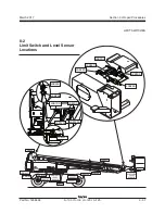
LIMIT SWITCHES
8-1
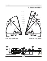
Limit Switches
How to Test the Limit Switches
There are 2 types of limit switches: Mechanical (roller
arm) and proximity. Mechanical limit switches
are activated by a part of the machine physically
moving the roller arm of the switch. Proximity
switches are a magnetic type of switch and are
activated by the close presence of a ferrous metal.
Mechanical Operational Limit Switch:
1 Manually activate the limit switch.
Result: The limit switch arm should move freely
and spring return to center. A distinct click
should be felt and heard.
2 Connect the leads from an ohmmeter or
continuity tester to the deutsch connector
terminals in the combination listed below and
check for continuity.
terminal 1 to 2
continuity
(zero
Ω
)
terminal 3 to 4
no continuity
(infinite
Ω
)
terminal 1 to 3 and 4
no continuity
(infinite
Ω
)
terminal 2 to 3 and 4
no continuity
(infinite
Ω
)
3 Activate the limit switch. Connect the leads from
an ohmmeter or continuity tester to the deutsch
connector terminals in the combination listed
below and check for continuity.
terminal 1 to 2
no continuity
(infinite
Ω
)
terminal 3 to 4
continuity
(zero
Ω
)
terminal 1 to 3 and 4
no continuity
(infinite
Ω
)
terminal 2 to 3 and 4
no continuity
(infinite
Ω
)
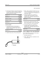
Mechanical Safety Limit Switch:
1 Connect the leads from an ohmmeter or
continuity tester to the deutsch connector
terminals in the combination listed below and
check for continuity.
terminal 1 to 2
continuity
(zero
Ω
)
terminal 3 to 4
continuity
(zero
Ω
)
terminal 1 to 3 and 4
no continuity
(infinite
Ω
)
terminal 2 to 3 and 4
no continuity
(infinite
Ω
)
terminal 5 to 6
no continuity
(infinite
Ω
)
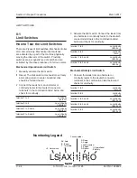
O Operational
S Safety
D Down
A Angle
L Load moment
E Extend
R Retract
Numbering Legend
LS AX 1 R O
LS Limit switch
AX Axle
B Boom
T Turntable
Circuit number
Summary of Contents for S-100
Page 246: ...March 2017 Section 6 Schematics 6 22 Safety Circuit Schematic 6 21 ...
Page 259: ...Section 6 Schematics March 2017 6 35 6 36 Electrical Schematic Generator Options ...
Page 262: ...March 2017 Section 6 Schematics 6 38 6 37 Electrical Schematic 12 kW Generator welder option ...
Page 264: ...March 2017 Section 6 Schematics 6 40 Perkins 1104D 44T Engine Electrical Schematic 6 39 ...
Page 265: ...Section 6 Schematics March 2017 6 41 Perkins 854F 34T Engine Electrical Schematic 6 42 ...
Page 268: ...March 2017 Section 6 Schematics 6 44 Perkins 854F 34T Engine Harness 6 45 ...
Page 269: ...Section 6 Schematics March 2017 6 45 Deutz TD2011L04i Engine Electrical Schematic 6 46 ...
Page 271: ...Section 6 Schematics March 2017 6 47 Deutz TD2 9 Engine Electrical Schematic 6 48 ...
Page 274: ...March 2017 Section 6 Schematics 6 50 Deutz TD2 9 Engine Electrical Harness 6 51 ...
Page 276: ...March 2017 Section 6 Schematics 6 52 6 53 Hydraulic Schematic 12 kW Generator welder option ...

