Part No. 1268494
S-100 • S-105 • S-120 • S-125
3 - 65
March 2017
Section 3 • Repair Procedures
LIMIT SWITCHES
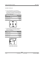
2 Activate the limit switch. Connect the leads from
an ohmmeter or continuity tester to the deutsch
connector terminals in the combination listed
below and check for continuity.
terminal 1 to 2
no continuity
(infinite
Ω
)
terminal 3 to 4
no continuity
(infinite
Ω
)
terminal 1 to 3 and 4
no continuity
(infinite
Ω
)
terminal 2 to 3 and 4
no continuity
(infinite
Ω
)
terminal 5 to 6
continuity
(zero
Ω
)
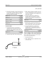
Proximity Switch:
1 Connect the leads from an ohmmeter or
continuity tester to the deutsch connector
terminals in the combination listed below and
check for continuity.
terminal 3 to 4
no continuity
(infinite
Ω
)
2 Locate the target area of the proximity switch.
Proximity switch
a
target area
a
3 Place a piece of ferrous metal (steel, iron, etc.)
in front of the target area so it is no more than
1
/
2
inch / 12.7 mm away from the target area of
the proximity switch.
4 Connect the leads from an ohmmeter or
continuity tester to the deutsch connector
terminals in the combination listed below and
check for continuity.
terminal 3 to 4
continuity
(zero
Ω
)
5 Move the piece of ferrous metal (steel, iron,
etc.) so it is more than
1
/
2
inch / 12.7 mm away
from the target area of the proximity switch.
6 Connect the leads from an ohmmeter or
continuity tester to the deutsch connector
terminals in the combination listed below and
check for continuity.
terminal 3 to 4
no continuity
(infinite
Ω
)
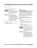
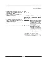
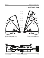
How to Adjust the Limit Switches
Note: Perform this procedure on a flat and level
area and free from obstructions.
1 Fully retract the boom.
2 Place a digital protractor or digital level on top
of the boom tube.
Summary of Contents for S-100
Page 246: ...March 2017 Section 6 Schematics 6 22 Safety Circuit Schematic 6 21 ...
Page 259: ...Section 6 Schematics March 2017 6 35 6 36 Electrical Schematic Generator Options ...
Page 262: ...March 2017 Section 6 Schematics 6 38 6 37 Electrical Schematic 12 kW Generator welder option ...
Page 264: ...March 2017 Section 6 Schematics 6 40 Perkins 1104D 44T Engine Electrical Schematic 6 39 ...
Page 265: ...Section 6 Schematics March 2017 6 41 Perkins 854F 34T Engine Electrical Schematic 6 42 ...
Page 268: ...March 2017 Section 6 Schematics 6 44 Perkins 854F 34T Engine Harness 6 45 ...
Page 269: ...Section 6 Schematics March 2017 6 45 Deutz TD2011L04i Engine Electrical Schematic 6 46 ...
Page 271: ...Section 6 Schematics March 2017 6 47 Deutz TD2 9 Engine Electrical Schematic 6 48 ...
Page 274: ...March 2017 Section 6 Schematics 6 50 Deutz TD2 9 Engine Electrical Harness 6 51 ...
Page 276: ...March 2017 Section 6 Schematics 6 52 6 53 Hydraulic Schematic 12 kW Generator welder option ...

