Part No. 1268494
S-100 • S-105 • S-120 • S-125
3 - 85
March 2017
Section 3 • Repair Procedures
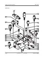
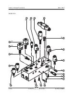
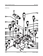
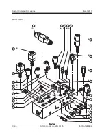
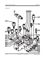
MANIFOLDS
10-3
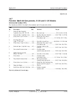
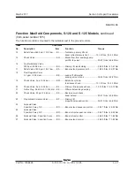
Valve Adjustments - Function
Manifold, S-100 and S-105 Models
How to Adjust the Function
Manifold Relief Valve
Note: Perform this procedure with the boom in the
stowed position.
1 Connect a 0 to 5000 psi / 0 to 345 bar pressure
gauge to the test port on the function manifold.
2 Start the engine from the ground controls.
3 Simultaneously push and hold the function
enable/high speed button and the boom
retract button with the boom fully retracted.
Observe the pressure reading on the pressure
gauge. Refer to Specifications,
Hydraulic Oil
Specifications.
4 Turn the engine off. Use a wrench to hold the
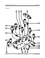
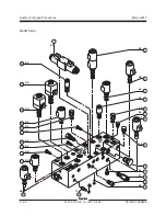
relief valve and remove the cap (item FI).
5 Adjust the internal hex socket. Turn it clockwise
to increase the pressure or counterclockwise to
decrease the pressure. Install the relief valve
cap.
Tip-over hazard. Do not adjust
the relief valve higher than
specified.
6 Repeat steps 2 through 5 to confirm the relief
valve pressure.
How to Adjust the Boom Extend
Relief Valve
Note: Perform this procedure with the boom in the
stowed position.
1 Connect a 0 to 3000 psi / 0 to 207 bar pressure
gauge to the test port on the function manifold.
2 Start the engine from the ground controls.
3 Fully raise and extend the boom.
4 Simultaneously push and hold the function
enable/high speed button and the boom
extend button with the boom fully extended.
Observe the pressure reading on the pressure
gauge. Refer to Specifications,
Hydraulic
Specifications.
5 Turn the engine off. Use a wrench to hold the
relief valve and remove the cap (item FA).
6 Adjust the internal hex socket. Turn it clockwise
to increase the pressure or counterclockwise to
decrease the pressure. Install the relief valve
cap.
Tip-over hazard. Do not adjust
the relief valve higher than
specified.
7 Repeat steps 2 through 6 to confirm the relief
valve pressure.
Summary of Contents for S-100
Page 246: ...March 2017 Section 6 Schematics 6 22 Safety Circuit Schematic 6 21 ...
Page 259: ...Section 6 Schematics March 2017 6 35 6 36 Electrical Schematic Generator Options ...
Page 262: ...March 2017 Section 6 Schematics 6 38 6 37 Electrical Schematic 12 kW Generator welder option ...
Page 264: ...March 2017 Section 6 Schematics 6 40 Perkins 1104D 44T Engine Electrical Schematic 6 39 ...
Page 265: ...Section 6 Schematics March 2017 6 41 Perkins 854F 34T Engine Electrical Schematic 6 42 ...
Page 268: ...March 2017 Section 6 Schematics 6 44 Perkins 854F 34T Engine Harness 6 45 ...
Page 269: ...Section 6 Schematics March 2017 6 45 Deutz TD2011L04i Engine Electrical Schematic 6 46 ...
Page 271: ...Section 6 Schematics March 2017 6 47 Deutz TD2 9 Engine Electrical Schematic 6 48 ...
Page 274: ...March 2017 Section 6 Schematics 6 50 Deutz TD2 9 Engine Electrical Harness 6 51 ...
Page 276: ...March 2017 Section 6 Schematics 6 52 6 53 Hydraulic Schematic 12 kW Generator welder option ...

