3 - 136
S-100 • S-105 • S-120 • S-125
Part No. 1268494
March 2017
Section 3 • Repair Procedures
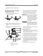
3 Mark the mounting position of the steer sensor
cover on the yoke.
Note: It is very important that the steer sensor
is installed in the exact position it was in prior
to removal. If the steer sensor is not installed
correctly, the steer function may operate
improperly. If any steer functions operate
improperly after removing and installing a steer
sensor, see 13-1,
How to Adjust a Steer Sensor.
4 Remove the steer sensor cover retaining
fasteners. Carefully remove the steer sensor
cover and lay it out of the way.
Component damage hazard. The
steer sensor is a very sensitive
instrument. It can be damaged
internally if it is dropped or
sustains any physical shock, even
if the damage is not visible.
5 Lay the hoses and steer sensor cable out of the
way.
Component damage hazard.
Cables and hoses can be
damaged if they are kinked or
pinched.
6 Mark the mounting position of the steer sensor
activator pin mounted to the top of the yoke
pivot pin.
7 Remove the steer sensor activator pin retaining
fasteners. Remove the steer sensor activator
pin from the machine.
Note: It is very important that the steer sensor
activator pin is installed in the exact position it was
in prior to removal. If the steer sensor activator pin
is not installed correctly, the steer function may
operate improperly. If any steer functions operate
improperly after removing and installing a steer
sensor activator pin, see 13-1,
How to Adjust a
Steer Sensor.
8 Loosen the wheel lug nuts. Do not remove
them.
9 Center a lifting jack of ample capacity under the
axle of the yoke and drive hub to be removed.
Do not raise the machine.
10 Block the wheels at the opposite end of the
machine.
11 Raise the machine approximately 6 inches
(15 cm) and place blocks under the chassis for
support.
12 Remove the lug nuts and remove the tire and
wheel assembly.
13 Remove the drive motor mounting fasteners.
14 Slide the drive motor shaft out of the drive hub
and remove the drive motor from the machine.
15 Remove the pin retaining fasteners from the
steering cylinder rod-end pivot pins. Remove
the pins.
16 Remove the pin retaining fasteners from the
upper and lower yoke pivot pins.
AXLE COMPONENTS
Summary of Contents for S-100
Page 246: ...March 2017 Section 6 Schematics 6 22 Safety Circuit Schematic 6 21 ...
Page 259: ...Section 6 Schematics March 2017 6 35 6 36 Electrical Schematic Generator Options ...
Page 262: ...March 2017 Section 6 Schematics 6 38 6 37 Electrical Schematic 12 kW Generator welder option ...
Page 264: ...March 2017 Section 6 Schematics 6 40 Perkins 1104D 44T Engine Electrical Schematic 6 39 ...
Page 265: ...Section 6 Schematics March 2017 6 41 Perkins 854F 34T Engine Electrical Schematic 6 42 ...
Page 268: ...March 2017 Section 6 Schematics 6 44 Perkins 854F 34T Engine Harness 6 45 ...
Page 269: ...Section 6 Schematics March 2017 6 45 Deutz TD2011L04i Engine Electrical Schematic 6 46 ...
Page 271: ...Section 6 Schematics March 2017 6 47 Deutz TD2 9 Engine Electrical Schematic 6 48 ...
Page 274: ...March 2017 Section 6 Schematics 6 50 Deutz TD2 9 Engine Electrical Harness 6 51 ...
Page 276: ...March 2017 Section 6 Schematics 6 52 6 53 Hydraulic Schematic 12 kW Generator welder option ...


