3 - 14
S-100 • S-105 • S-120 • S-125
Part No. 1268494
March 2017
Section 3 • Repair Procedures
Function speeds:
Note: Be sure the machine is in the stowed
position and the boom is rotated between the circle
end tires.
Note: Perform this procedure with the machine
parked on a firm, level surface which is free of
obstructions.
12 Start the engine from the platform controls.
13 Select a boom function that needs the function
speed set.
14
Boom up/down functions:
Starting in the
stowed position, move the joystick full stroke
in the up direction. When the alarm sounds,
move the joystick in the opposite direction full
stroke until the alarm sounds again. Return the
joystick to center.
Boom extend/retract functions:
Raise the
boom until the low-speed drive function is
enabled. Move the joystick full stroke in the
extend direction. When the alarm sounds,
move the joystick in the opposite direction full
stroke until the alarm sounds again. Return the
joystick to center.
Turntable rotate functions:
Raise the boom
until the low-speed drive function is enabled.
Move the joystick full stroke to the left (cw) until
the drive enable light turns on. Then move the
joystick full stroke to the right (ccw). When the
alarm sounds, move the joystick in the opposite
direction full stroke until the alarm sounds
again. Return the joystick to center.
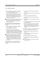
15 Once all the joystick controllers have been
calibrated, push in the red Emergency Stop
button at the platform controls to save the
settings in memory.
Note: The red Emergency Stop button at the
platform controls must be pushed in to the off
position following calibration of the joystick
controllers to save the settings in memory.
16 At the ground controls, turn the key switch to
the off position, wait a moment and then turn
the key switch to platform controls.
17 Check the display at the ground controls to be
sure there are no calibration faults.
Note: There should be no calibration faults shown
on the display. If calibration faults exist, repeat this
procedure.
How to Adjust the Function
Speeds
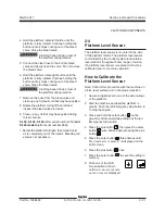
1 Pull out the red Emergency Stop button to the
on position at both the ground and platform
controls.
PLATFORM CONTROLS
REV B
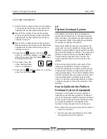
7 While holding the joystick in position, press the
engine start button
at the platform controls
to set the joystick controller threshold.
8 Repeat steps 3 through 7 for each joystick
controlled machine function (boom up/down
and turntable rotate left/right, boom extend/
retract, and drive forward/reverse).
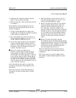
9 Once all the joystick controllers have been
calibrated, push in the Emergency Stop button
at the platform controls to save the settings in
memory.
Note: The red Emergency Stop button at the
platform controls must be pushed in to the off
position following calibration of the joystick
controllers to save the settings in memory.
10 At the ground controls, turn the key switch to
the off position, wait a moment and then turn
the key switch to platform controls.
11 Check the display at the ground controls to be
sure there are no calibration faults.
Note: There should be no calibration faults shown
on the display. If calibration faults exist, repeat this
procedure.
Summary of Contents for S-100
Page 246: ...March 2017 Section 6 Schematics 6 22 Safety Circuit Schematic 6 21 ...
Page 259: ...Section 6 Schematics March 2017 6 35 6 36 Electrical Schematic Generator Options ...
Page 262: ...March 2017 Section 6 Schematics 6 38 6 37 Electrical Schematic 12 kW Generator welder option ...
Page 264: ...March 2017 Section 6 Schematics 6 40 Perkins 1104D 44T Engine Electrical Schematic 6 39 ...
Page 265: ...Section 6 Schematics March 2017 6 41 Perkins 854F 34T Engine Electrical Schematic 6 42 ...
Page 268: ...March 2017 Section 6 Schematics 6 44 Perkins 854F 34T Engine Harness 6 45 ...
Page 269: ...Section 6 Schematics March 2017 6 45 Deutz TD2011L04i Engine Electrical Schematic 6 46 ...
Page 271: ...Section 6 Schematics March 2017 6 47 Deutz TD2 9 Engine Electrical Schematic 6 48 ...
Page 274: ...March 2017 Section 6 Schematics 6 50 Deutz TD2 9 Engine Electrical Harness 6 51 ...
Page 276: ...March 2017 Section 6 Schematics 6 52 6 53 Hydraulic Schematic 12 kW Generator welder option ...

