Part No. 1268494
S-100 • S-105 • S-120 • S-125
3 - 15
March 2017
Section 3 • Repair Procedures
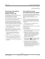
PLATFORM CONTROLS
Specifications
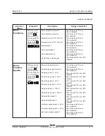
Ramp rate (factory settings)
Turntable rotate
accelerate
2 seconds
decelerate
0.25 second
Primary boom up/down
accelerate
3 seconds
decelerate
0..25 second
Primary boom extend/retract
accelerate
2 seconds
decelerate
0.25 second
Jib boom up/down
accelerate
2 seconds
decelerate
0.25 second
Drive
accelerate
2 seconds
REV B
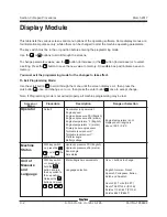
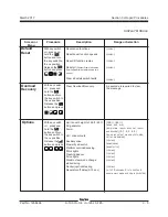
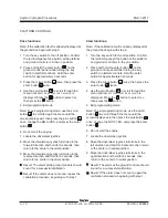
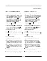
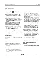
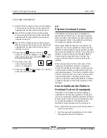
2 Press and hold the enter button
on the
ground control panel while turning the key
switch to ground controls. Hold the enter
button for approximately 5 seconds.
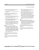
3 Press the plus button
twice, then press the
minus button
twice.
4 Press the scroll button until the function to
be adjusted is displayed.
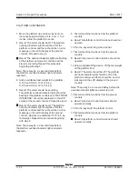
5 Press the plus button
to increase the speed
or press the minus button
to decrease the
speed.
6 Press the enter button
to save the setting in
memory.
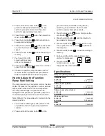
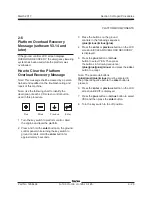
7 Push one of the LCD
screen buttons shown
until
exit
is displayed.
8 Press the plus
button to select
yes
and then
press the enter button
.
9 Continue to perform this procedure until the
machine function speed meets specification.
Refer to
Specifications
for function speeds.
How to Adjust the Function
Ramp Rate Setting
The ramp rate setting of a joystick controls the time
at which it takes for the joystick to reach maximum
output, when moved out of the neutral position.
The ramp rate settings of a joystick can be
changed to compensate for hydraulic pump wear
to maintain peak performance from the machine.
Note: Perform this procedure with the boom in the
stowed position.
1 Pull out the red Emergency Stop button to the
on position at both the ground and platform
controls.
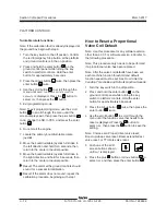
2 Press and hold the enter button
on the
ground control panel while turning the key
switch to ground controls. Hold the enter
button for approximately 5 seconds.
3 Press the plus button
twice, then press the
scroll button twice.
4 Press the scroll button until the function to
be adjusted is displayed.
5 Press the plus button
to increase the ramp
rate or press the minus button
to decrease
the ramp rate.
6 Press the enter button
to save the setting in
memory.
7 Push one of the LCD screen buttons shown
until
exit
is displayed.
8 Press the plus
button to select
yes
and
then press the enter button
.
Summary of Contents for S-100
Page 246: ...March 2017 Section 6 Schematics 6 22 Safety Circuit Schematic 6 21 ...
Page 259: ...Section 6 Schematics March 2017 6 35 6 36 Electrical Schematic Generator Options ...
Page 262: ...March 2017 Section 6 Schematics 6 38 6 37 Electrical Schematic 12 kW Generator welder option ...
Page 264: ...March 2017 Section 6 Schematics 6 40 Perkins 1104D 44T Engine Electrical Schematic 6 39 ...
Page 265: ...Section 6 Schematics March 2017 6 41 Perkins 854F 34T Engine Electrical Schematic 6 42 ...
Page 268: ...March 2017 Section 6 Schematics 6 44 Perkins 854F 34T Engine Harness 6 45 ...
Page 269: ...Section 6 Schematics March 2017 6 45 Deutz TD2011L04i Engine Electrical Schematic 6 46 ...
Page 271: ...Section 6 Schematics March 2017 6 47 Deutz TD2 9 Engine Electrical Schematic 6 48 ...
Page 274: ...March 2017 Section 6 Schematics 6 50 Deutz TD2 9 Engine Electrical Harness 6 51 ...
Page 276: ...March 2017 Section 6 Schematics 6 52 6 53 Hydraulic Schematic 12 kW Generator welder option ...

