3 - 22
S-100 • S-105 • S-120 • S-125
Part No. 1268494
March 2017
Section 3 • Repair Procedures
2-5
Platform Overload System
The platform overload system is designed to
prevent the machine from continuing to operate
when the load in the platform exceeds maximum
rated capacity. Refer to the machine serial label
for maximum capacity information.
If maximum platform capacity is exceeded, the
alarm will sound at the platform controls and the
platform overload indicator lights will flash at both
the ground and platform controls. The ground and
platform controls will become disabled. Before
normal machine operation can continue, the
excess load will need to be removed from the
platform.
If the excess load cannot be removed or if the
operator at the platform controls is unable to
correct the overloaded condition, another person
at the ground controls can operate the machine
using auxiliary power. There will be limited control
of boom functions from the ground controls when
using auxiliary power. Auxiliary power can be
used to correct the overloaded platform condition
in order to resume normal, safe operation of the
machine.
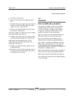
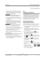
How to Calibrate the Platform
Overload System (if equipped)
Calibration of the platform overload system is
essential to safe machine operation. Continued
use of an improperly calibrated platform overload
system could result in the system failing to sense
an overloaded platform. The stability of the
machine is compromised and it could tip over.
Note: Perform this procedure with the machine on
a firm, level surface.
1 Turn the key switch to platform control. Start
the engine and level the platform.
PLATFORM COMPONENTS
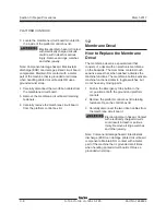
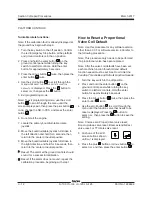
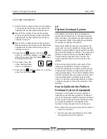
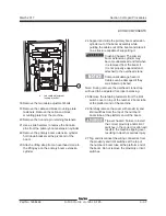
9 Confirm that the number shown on the display
is the same as that shown on the data sheet
supplied with the new platform level sensor.
Result: If the number shown on the display
is the same as that shown on the data sheet
supplied with the new platform level sensor,
continue to step 10.
Result: If the number shown on the display is
not
the same as that shown on the data sheet
supplied with the new platform level sensor,
continue to step 9.
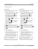
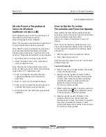
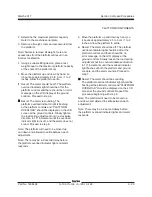
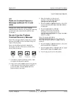
10 Press the plus
button or the minus
button to correct the display to match the data
sheet. Then press the enter button
to save
the setting in memory.
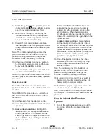
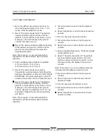
11 Push one of the LCD
screen buttons shown
until
exit
is displayed.
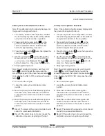
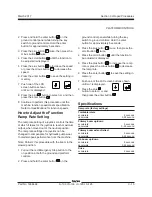
11 Press the plus
button to select
yes
and then
press the enter button
.
Summary of Contents for S-100
Page 246: ...March 2017 Section 6 Schematics 6 22 Safety Circuit Schematic 6 21 ...
Page 259: ...Section 6 Schematics March 2017 6 35 6 36 Electrical Schematic Generator Options ...
Page 262: ...March 2017 Section 6 Schematics 6 38 6 37 Electrical Schematic 12 kW Generator welder option ...
Page 264: ...March 2017 Section 6 Schematics 6 40 Perkins 1104D 44T Engine Electrical Schematic 6 39 ...
Page 265: ...Section 6 Schematics March 2017 6 41 Perkins 854F 34T Engine Electrical Schematic 6 42 ...
Page 268: ...March 2017 Section 6 Schematics 6 44 Perkins 854F 34T Engine Harness 6 45 ...
Page 269: ...Section 6 Schematics March 2017 6 45 Deutz TD2011L04i Engine Electrical Schematic 6 46 ...
Page 271: ...Section 6 Schematics March 2017 6 47 Deutz TD2 9 Engine Electrical Schematic 6 48 ...
Page 274: ...March 2017 Section 6 Schematics 6 50 Deutz TD2 9 Engine Electrical Harness 6 51 ...
Page 276: ...March 2017 Section 6 Schematics 6 52 6 53 Hydraulic Schematic 12 kW Generator welder option ...

