3 - 30
S-100 • S-105 • S-120 • S-125
Part No. 1268494
March 2017
Section 3 • Repair Procedures
4-1
Cable Track
The cable track and boom cable tube guides
cables and hoses running up the boom. The
cable track can be repaired link by link without
removing the cables and hoses that run through
it. Removing the entire cable track assembly may
be necessary when performing major repairs that
involve removing the boom.
How to Remove the Boom
Cable Track
Note: When removing a hose assembly or fitting,
the O-ring on the fitting and/or hose end must be
replaced and then torqued to specification during
installation.
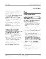
Refer to Specifications,
Hydraulic Hose and Fitting
Torque Specifications.
Note: Perform this procedure with the boom fully
stowed.
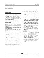
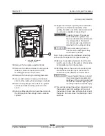
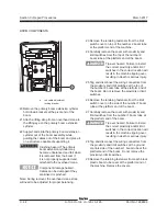
1 Remove the hose and cable cover retaining
fasteners from the jib boom leveling arm.
Remove the hose and cable cover from the
machine.
2 Remove the protective coil sleeve from the
hose and cable bundle at the platform end of
the boom cable tube.
3 Tag, disconnect and plug all hydraulic hoses
from the boom cable tube to the platform
manifold.
Note: If your machine is equipped with an airline
to platform option and/or weld cable option, the
airline and/or cable must be disconnected from the
platform before the cable track is removed.
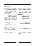
4 Tag and disconnect the black electrical
connector from the bottom of the control box.
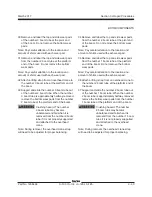
5 Remove the platform-end boom cable tube
mounting fasteners at the engine side of the
machine.
6 Remove the cable track mounting fasteners
from the cable track support at the engine side
of the machine.
7 Remove the wear pad mounting weldment from
the cable track support bracket at the engine
side of the machine.
8 Remove the hose and cable clamp from the
cable track support bracket at the engine side
of the machine.
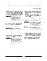
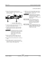
9 Place blocks between the cable track and the
boom cable tube for support.
10 Strap together the boom cable tube, blocks of
wood, and the cable track at the engine side of
the machine.
Component damage hazard.
Cables, hoses, boom cable tube
and cable track can be damaged if
they are kinked or pinched.
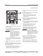
11 Remove the limit switch cover retaining
fasteners from the top of the number 2 boom
tube at the platform end of the machine.
Remove the limit switch cover.
12 Tag and disconnect the wiring connectors from
the proximity and limit switches on top of the
number 2 boom tube at the platform end of the
machine.
BOOM COMPONENTS
Summary of Contents for S-100
Page 246: ...March 2017 Section 6 Schematics 6 22 Safety Circuit Schematic 6 21 ...
Page 259: ...Section 6 Schematics March 2017 6 35 6 36 Electrical Schematic Generator Options ...
Page 262: ...March 2017 Section 6 Schematics 6 38 6 37 Electrical Schematic 12 kW Generator welder option ...
Page 264: ...March 2017 Section 6 Schematics 6 40 Perkins 1104D 44T Engine Electrical Schematic 6 39 ...
Page 265: ...Section 6 Schematics March 2017 6 41 Perkins 854F 34T Engine Electrical Schematic 6 42 ...
Page 268: ...March 2017 Section 6 Schematics 6 44 Perkins 854F 34T Engine Harness 6 45 ...
Page 269: ...Section 6 Schematics March 2017 6 45 Deutz TD2011L04i Engine Electrical Schematic 6 46 ...
Page 271: ...Section 6 Schematics March 2017 6 47 Deutz TD2 9 Engine Electrical Schematic 6 48 ...
Page 274: ...March 2017 Section 6 Schematics 6 50 Deutz TD2 9 Engine Electrical Harness 6 51 ...
Page 276: ...March 2017 Section 6 Schematics 6 52 6 53 Hydraulic Schematic 12 kW Generator welder option ...

