Part No. 1268494
S-100 • S-105 • S-120 • S-125
3 - 31
March 2017
Section 3 • Repair Procedures
BOOM COMPONENTS
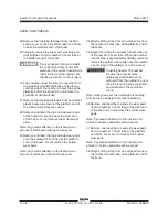
13 Remove the cable track roller guide mounting
fasteners from the ground controls side of the
machine at the platform end.
14 Remove the roller guide from the cable
track guide bracket at the engine side of the
machine.
15 Tag, disconnect and plug the hydraulic hoses
from the bottom of the bulkhead fittings on the
cable track support at the ground controls side
of the machine.
Bodily injury hazard. Spraying
hydraulic oil can penetrate and
burn skin. Loosen hydraulic
connections very slowly to allow
the oil pressure to dissipate
gradually. Do not allow oil to
squirt or spray.
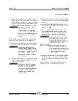
16 Remove the bulkhead fitting locknuts from the
bulkhead fittings on the cable track support
at the ground controls side of the machine.
Remove and cap the fittings.
17 Tag and disconnect the wiring connectors.
Note: The wiring connectors that need to be
disconnected are located next to the hose fittings
that were removed in step 16.
If not removing the boom from the machine,
proceed to step 19.
18 Tag, disconnect and plug the primary extension
cylinder hydraulic hoses on the side of the
number 2 boom tube at the ground controls
side of the machine. Cap the fittings.
Bodily injury hazard. Spraying
hydraulic oil can penetrate and
burn skin. Loosen hydraulic
connections very slowly to allow
the oil pressure to dissipate
gradually. Do not allow oil to
squirt or spray.
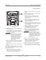
19 Remove the cable track mounting fasteners
from the cable track support at the ground
controls side of the machine.
20 Remove the side panels from the boom cable
tube located under the cable track at the
ground controls side of the machine.
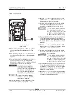
21 Remove the hose and cable cover mounting
fasteners from the pivot end of the boom at the
ground controls side of the machine. Remove
the cover.
22 Remove the hose and cable clamps from the
hoses and cables located below the boom pivot
on the inside of the turntable riser at the ground
controls side of the machine.
23 Tag and disconnect the electrical cables from
the cable track to the ground controls side of
the machine.
Summary of Contents for S-100
Page 246: ...March 2017 Section 6 Schematics 6 22 Safety Circuit Schematic 6 21 ...
Page 259: ...Section 6 Schematics March 2017 6 35 6 36 Electrical Schematic Generator Options ...
Page 262: ...March 2017 Section 6 Schematics 6 38 6 37 Electrical Schematic 12 kW Generator welder option ...
Page 264: ...March 2017 Section 6 Schematics 6 40 Perkins 1104D 44T Engine Electrical Schematic 6 39 ...
Page 265: ...Section 6 Schematics March 2017 6 41 Perkins 854F 34T Engine Electrical Schematic 6 42 ...
Page 268: ...March 2017 Section 6 Schematics 6 44 Perkins 854F 34T Engine Harness 6 45 ...
Page 269: ...Section 6 Schematics March 2017 6 45 Deutz TD2011L04i Engine Electrical Schematic 6 46 ...
Page 271: ...Section 6 Schematics March 2017 6 47 Deutz TD2 9 Engine Electrical Schematic 6 48 ...
Page 274: ...March 2017 Section 6 Schematics 6 50 Deutz TD2 9 Engine Electrical Harness 6 51 ...
Page 276: ...March 2017 Section 6 Schematics 6 52 6 53 Hydraulic Schematic 12 kW Generator welder option ...


